Adjustable length punch assembly

a technology of adjustable length and punch, which is applied in the field of metal working tools, can solve the problems of natural dulling and wear of the punch tip, shortening the length of the punch,

Inactive Publication Date: 2007-01-30
WILSON TOOL INT
View PDF35 Cites 50 Cited by
  • Summary
  • Abstract
  • Description
  • Claims
  • Application Information

AI Technical Summary

Problems solved by technology

Repeated use of a punch assembly in a punch press operation results in the natural dulling and wear of the punch tip.
Sharpening may be accomplished by grinding the end of the punch tip, and this results in shortening the length of the punch.

Method used


Image

  • Adjustable length punch assembly
  • Adjustable length punch assembly
  • Adjustable length punch assembly

Examples


Embodiment Construction

[0019]The following detailed description should be read with reference to the drawings, in which like elements in different drawings are numbered identically. The drawings, which are not necessarily to scale, depict selected embodiments and are not intended to limit the scope of the invention. Examples of constructions, materials, dimensions, and manufacturing processes are provided for selected elements. All other elements employ that which is known to those of skill in the field of the invention. Those skilled in the art will recognize that many of the examples provided have suitable alternatives that can be utilized.

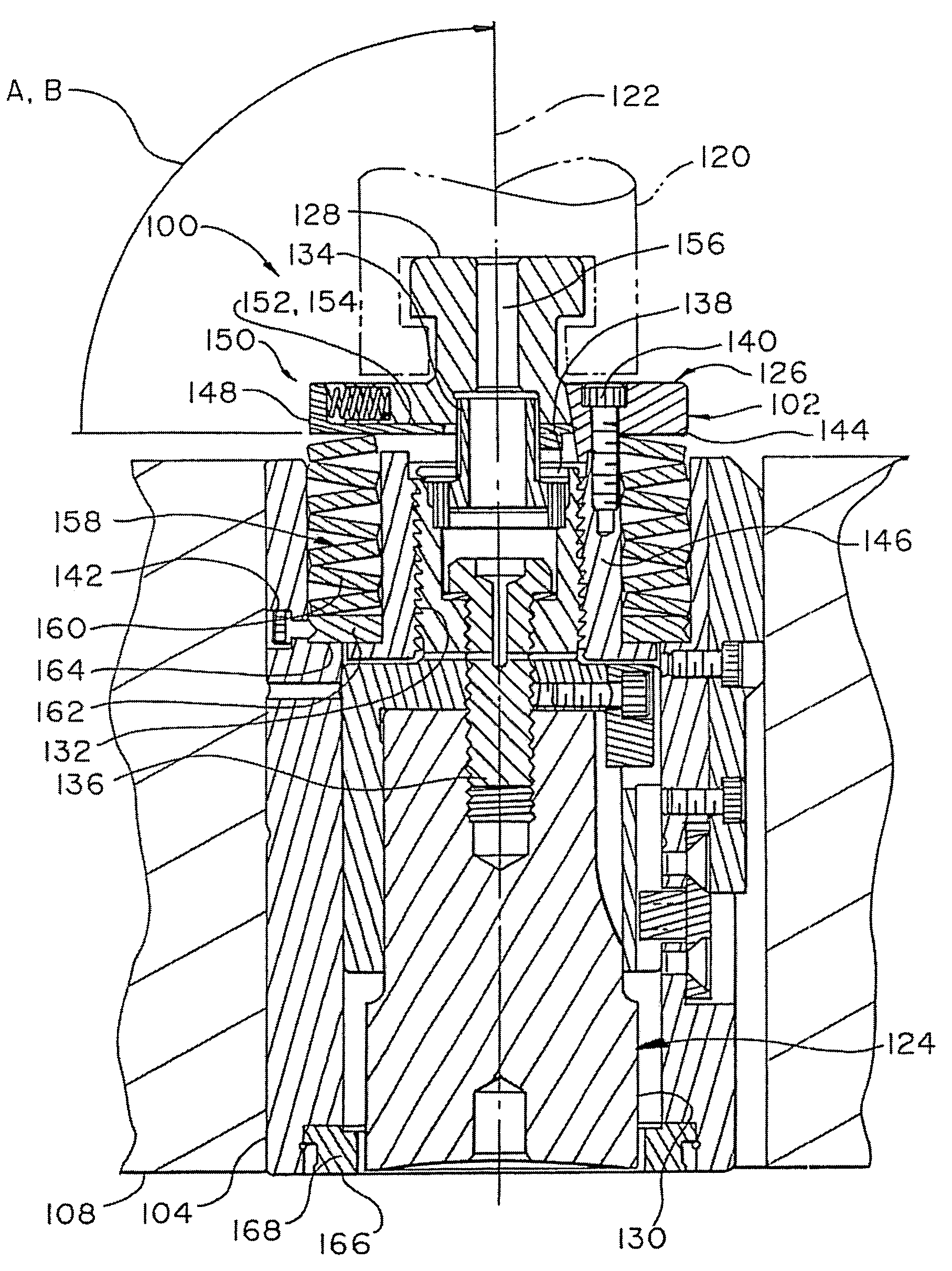
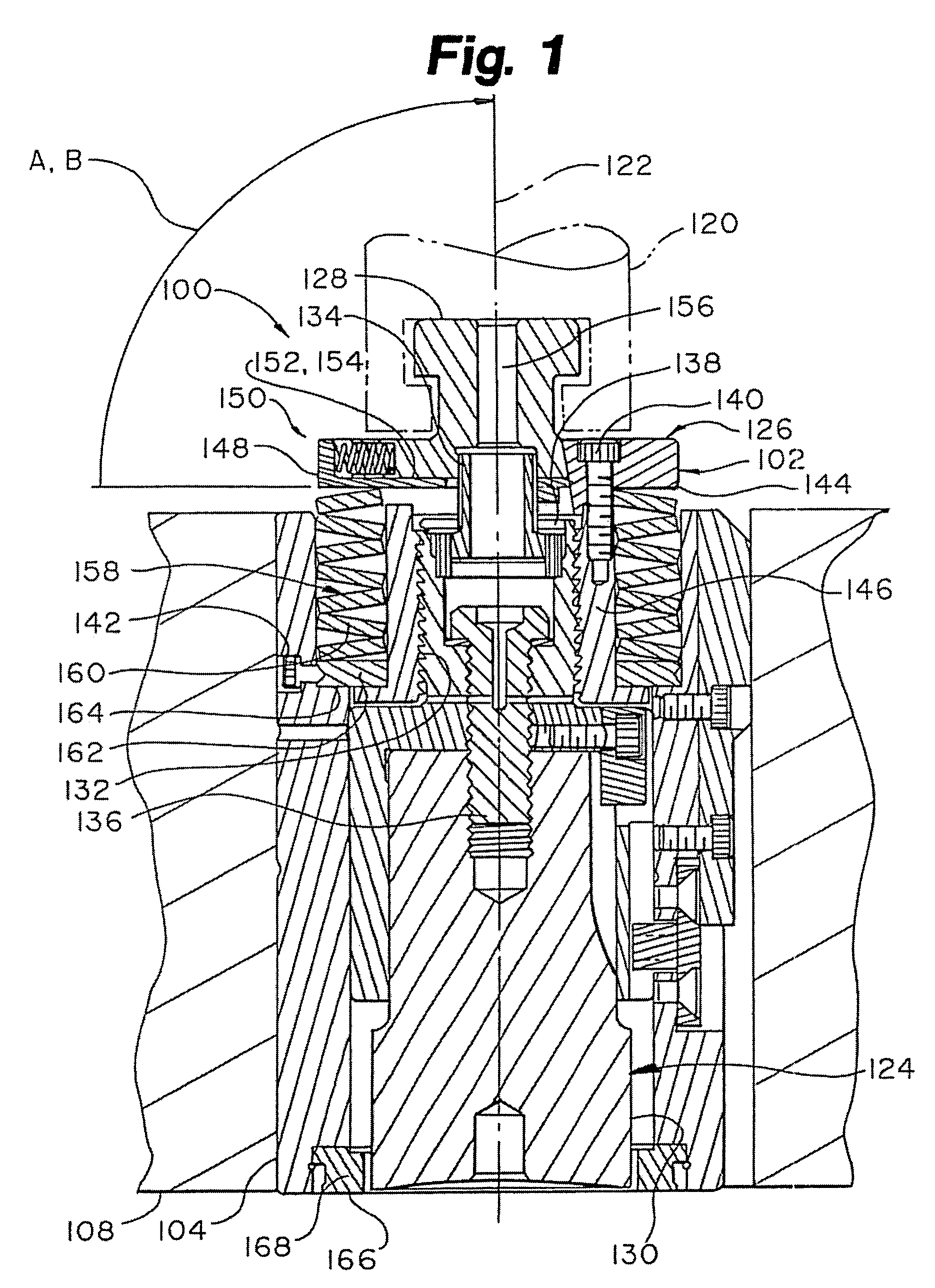
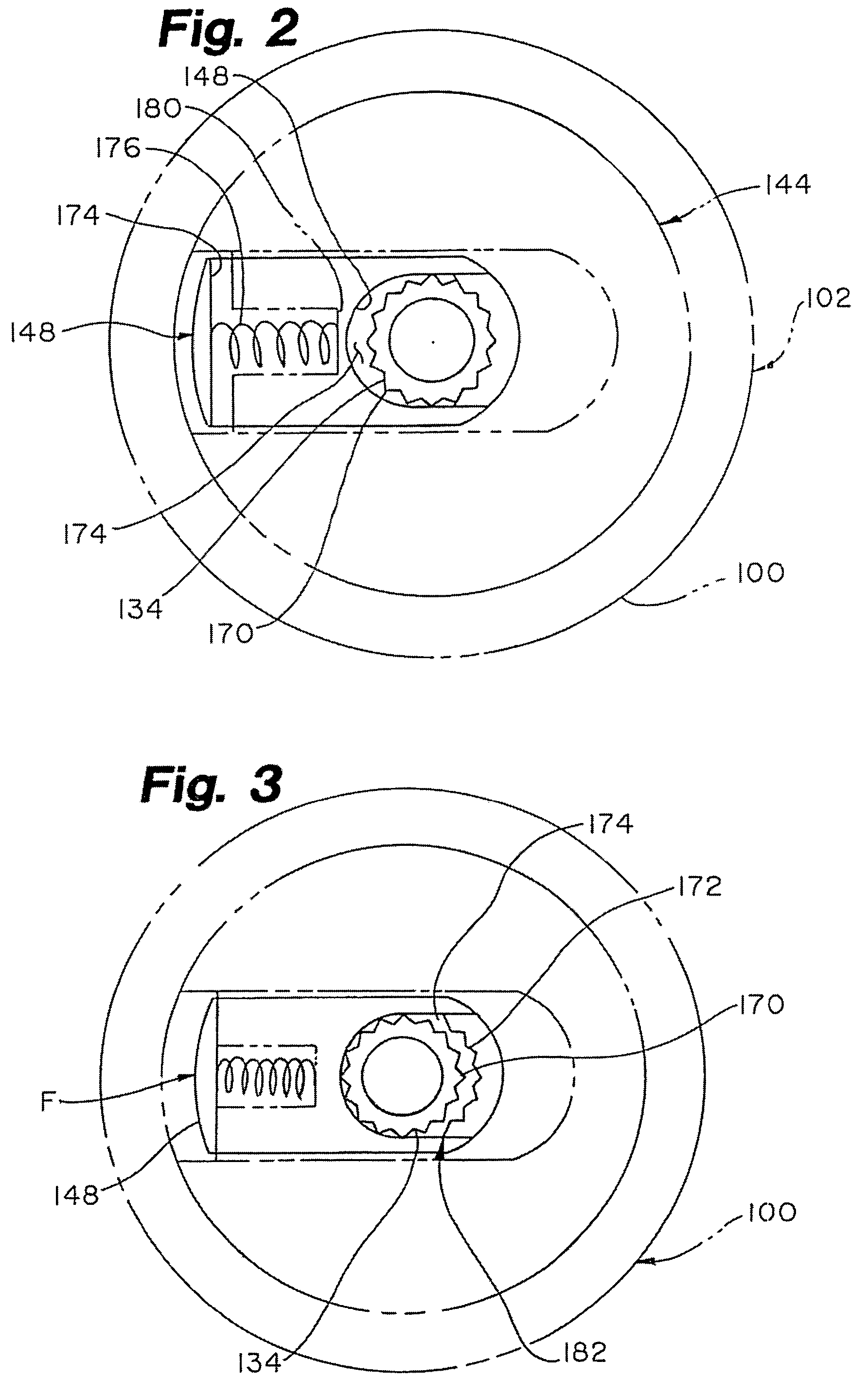
[0020]FIG. 1 is a cross sectional view of a punch set assembly 100 in accordance with an exemplary embodiment of the present invention. Punch set assembly 100 includes a sleeve 104 and an adjustable length punch assembly 102 that is slidingly disposed within sleeve 104. Punch set assembly 100 may be used in a punch press including a tool holder 108 adapted to receive ...


PUM

PropertyMeasurementUnit
lengthaaaaaaaaaa
angleaaaaaaaaaa
perimeteraaaaaaaaaa

Abstract

Adjustable length punch assemblies are disclosed. An adjustable length punch assembly in accordance with present invention may be used with a punch press including a tool holder adapted to receive punch assembly and a ram adapted to move longitudinally along a ram axis. An adjustable length punch assembly in accordance with present invention preferably includes a punch body assembly disposed in threading engagement with a drive body assembly having a surface adapted to be struck by ram of punch press. The length of punch assembly may be adjusted by rotating of one body relative to other body. The adjustable length punch assembly preferably includes a lock mechanism for selectively preventing rotation of the punch body assembly relative to the drive body assembly. The lock mechanism preferably comprises a lock shaft coupled to one of bodies and a lock key slidingly coupled to other of bodies such that lock key slides along a lock key path. The lock key path is preferably disposed at an angle relative to ram axis when punch assembly is received by tool holder.

Description

[0001]This is a Continuation of application Ser. No. 10 / 841,853 filed May 7, 2004, now abandoned which in turn is a continuation application of application Ser. No. 09 / 884,237 filed Jun. 19, 2001 (now U.S. Pat. No. 6,755,110).FIELD OF THE INVENTION[0002]The present invention relates generally to metal working tools. More particularly, the present invention relates to punch assemblies used in punch presses.BACKGROUND OF THE INVENTION[0003]Sheet metal may be economically fabricated into a wider range of useful products including chassis for appliances and electrical devices. Turret-type punch presses have found wide use in fabricating sheet metal. Turret-type punch presses employ an upper, generally cylindrical turret which holds a series of punch tools spaced circumferentially around its periphery, and a second, lower turret holding a series of dies circumferentially spaced about that turret's periphery, each turret being rotatable about a vertical axis to bring an appropriate punch ...

Claims


Application Information

Patent Timeline
Patent Type & Authority Patents(United States)
IPC IPC(8): B26F1/14A10H5/02B21D28/34
CPCB21D28/34Y10T83/8732Y10T83/9486Y10T83/9478Y10T83/9476Y10T83/9428
Inventor ROSENE, RONALD G.SHULDES, GLEN MTIMP, RICHARD L.PELOQUIN, WAYNE F.RUNK, DAVID M.
Owner WILSON TOOL INT
Why Eureka
Try Eureka