Putter head

a club head and putter head technology, applied in the field of putter head, can solve the problems of reducing the qualified product ratio, reducing the accuracy of striking, and difficulty in subsequent processing of the body b>10/b>, so as to reduce the striking error, improve the striking accuracy, and increase the inertia moment

Inactive Publication Date: 2007-01-30
FUSHENG IND CO LTD
View PDF8 Cites 32 Cited by
  • Summary
  • Abstract
  • Description
  • Claims
  • Application Information

AI Technical Summary

Benefits of technology

[0006]An object of the present invention is to provide a putter head including a light insert behind a face portion of the body of the putter head, allowing adjustment of the center of gravity of the club head. The putter head also includes an alignment means behind the face portion, assisting a golfer in properly aiming a golf ball toward a hole when putting. Thus, the striking error is reduced and the striking accuracy is improved. Further, the club head provides increased inertia moment, increasing the striking stability.SUMMARY OF THE INVENTION

Problems solved by technology

The striking accuracy is thus adversely affected.
Subsequent processing of the body 10 is difficult, and the qualified product ratio is decreased.

Method used


Image

  • Putter head
  • Putter head
  • Putter head

Examples


first embodiment

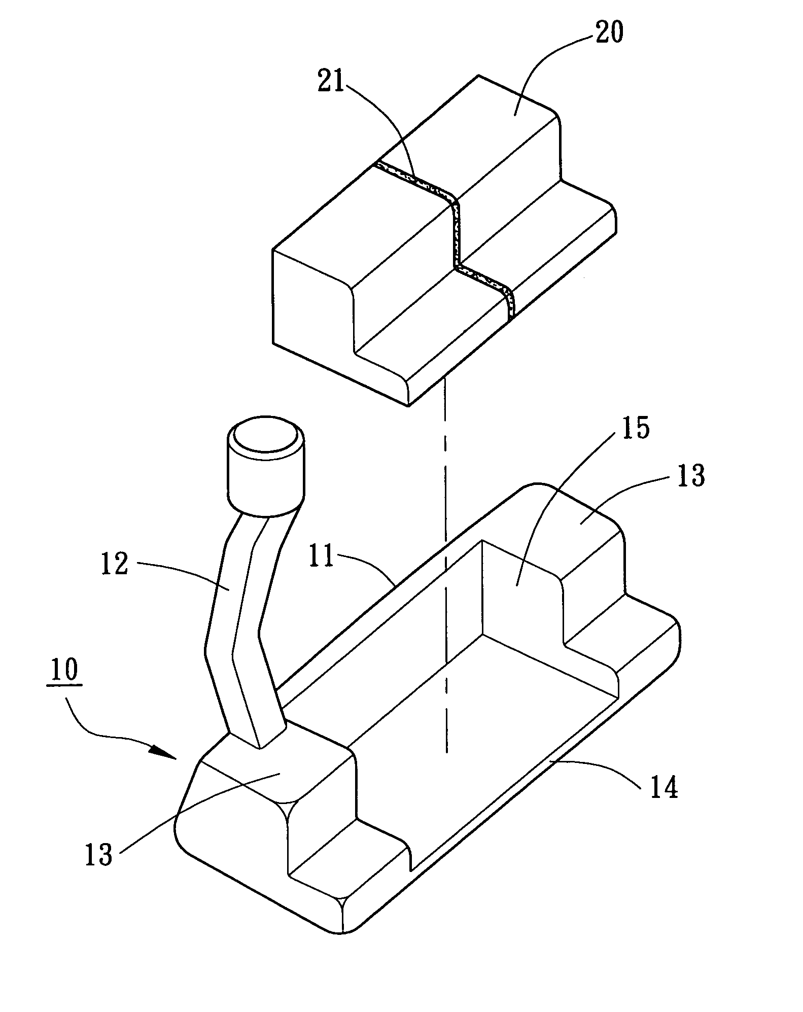
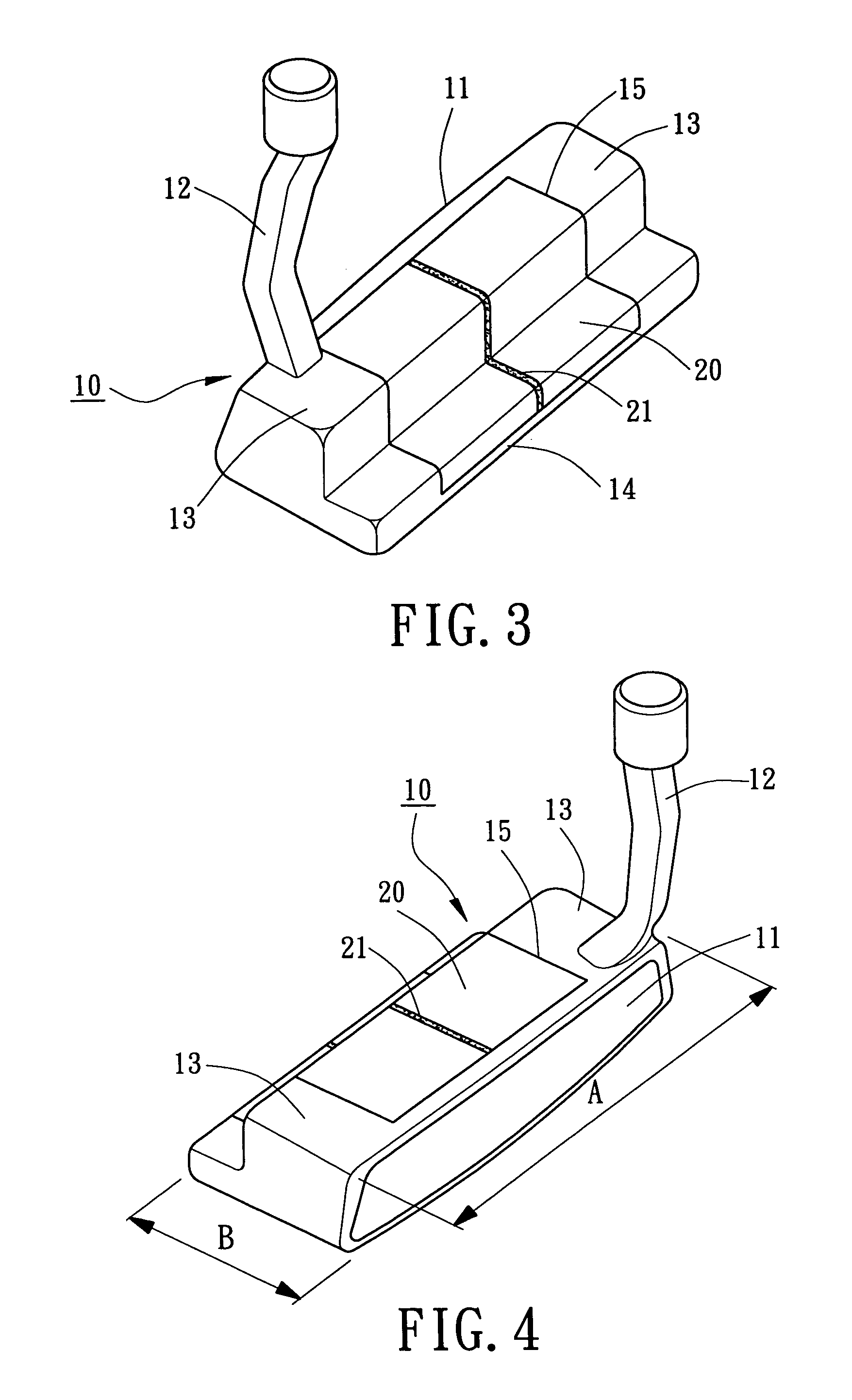
[0019]Referring to FIGS. 3 through 5, a putter head (i.e., putter type club head) in accordance with the present invention comprises a body 10 and a light insert 20. The body 10 is a putter-type body and made of stainless steel, carbon steel, titanium alloy, or copper alloy. The body 10 includes a face portion 11, a hosel 12, two mass portions 13, a connecting portion 14, and a compartment 15. The face portion 10 is located on a front side of the body 10 for striking a golf ball (not shown). The hosel 12 is located on an end of the top side of the body 10 for engaging with a shaft (not shown).

[0020]The mass portions 13 are preferably L-shaped and located on two sides of the body 10 and contribute to the weight of the body 10. The connecting portion 14 provides connection between the mass portions 13 to provide the club head with increased inertia moment. The connecting portion 14 has a thickness smaller than 2 mm, preferably smaller than 1 mm, and is most preferably 0.5 mm. The conn...

second embodiment

[0025]FIG. 7 illustrates the putter head in accordance with the present invention. In this embodiment, a rear end of the compartment 15 extends upward to prevent the light insert 20 from disengaging from the body 10 via the rear side of the compartment 15. Thus, the bonding reliability of the light insert 20 in the compartment 15 is improved.

third embodiment

[0026]FIGS. 8 and 9 illustrate the putter head in accordance with the present invention. In this embodiment, the connecting portion 14 includes an extension 16 extending rearward therefrom, with an aft-mass portion 17 being formed on a rear end of the extension 16, providing a substantially T-shaped body 10. Preferably, the width “A” of the body 10 is greater than the length “B” of the body 10. Further, the light insert 20 includes at least one aiming mark 21 on a top face thereof. The aiming mark 21 may be rectilinear, arrow-shaped, circular, oval, or triangular. Thus, the center of the club head is positioned within the light insert 20 through arrangement of the body 10 and the light insert 20. The center of gravity of the club head of this embodiment is located behind that of the club head of the previous embodiments. Further, the triangular mass distribution of the mass portions 13 and the aft-mass portion 17 of the body 10 provides the putter head with increased inertia moment,...


PUM


Abstract

A putter head includes a body and a light insert. The body includes a face portion, two mass portions, and a connecting portion. The face portion is located on a front side of the body, the mass portions are located on two sides of the body, and the connecting portion is formed between the mass portions for connecting the mass portions, with a compartment being defined between the mass portion and the connecting portion. The light insert is securely mounted in the compartment of the body. The light insert includes at least one aiming mark on a top face thereof. Further, the club head has a center of gravity positioned within the light insert.

Description

BACKGROUND OF THE INVENTION[0001]1. Field of the Invention[0002]The present invention relates to a putter-type club head. In particular, the present invention relates to a putter-type club head including a light insert for adjusting a center of gravity and an alignment means for aiming a golf ball during putting.[0003]2. Description of Related Art[0004]U.S. Pat. Nos. 6,471,600 and 6,506,125, as illustrated in FIGS. 1 and 2 of the drawings, disclose a putter head comprising a body 10 that includes a face portion 11, a hosel (cylindrical rod) 12, a crown portion 101, a sole portion 102, an aft-mass portion 103, a central aperture 104, and an alignment means 105. The central aperture 105 extends through the body 10 and has a heel opening at a heel end of the body 22 and a toe opening at a toe end of the body 22. The alignment means 105 assist a golfer in properly aiming a golf ball toward a hole when putting. The center of gravity of the club head is positioned within the central apert...

Claims


Application Information

Patent Timeline
Patent Type & Authority Patents(United States)
IPC IPC(8): A63B53/04A63B102/32
CPCA63B53/0487A63B2053/0491A63B2053/0441A63B60/02A63B53/0441
Inventor HOU, WEN-CHING
Owner FUSHENG IND CO LTD
Why Eureka
Try Eureka