Circuit with variable capacitance and method for operating a circuit with variable capacitance

a technology of capacitance and circuit, which is applied in the direction of electrial characteristics varying frequency control, pulse generator, pulse technique, etc., can solve the problem of not being able to produce such a voltage control oscillator at a low price, considerable hardware expenditure, and relatively short characteristic tuning curve generated therefrom, so as to avoid switching between individual characteristic curves and avoid shortening the characteristic tuning curve.

Active Publication Date: 2007-01-30
INFINEON TECH AG
View PDF6 Cites 6 Cited by
  • Summary
  • Abstract
  • Description
  • Claims
  • Application Information

AI Technical Summary

Benefits of technology

[0013]It is an object of the present invention to provide a circuit with variable capacitance and a method for operating a circuit with variable capacitance which allow a variable capacitance so that a more linear and flatter characteristic tuning curve may be provided as compared to a characteristic tuning curve of a conventional circuit. Further, it is an object of the present invention to provide a way to make a steepness of the characteristic tuning curve of the circuit variable. Further, it is the object of the present invention to provide an oscillator circuit and a method for operating an oscillator circuit, so that a variable adjustability of an output frequency of the oscillator circuit is made possible, and / or so that a more linear and flatter characteristic tuning curve of an oscillator circuit is provided as compared to a characteristic tuning curve of a conventional oscillator circuit. Further, it is an object of the present invention to provide a way to make a steepness of the characteristic tuning curve of the oscillator circuit variable.
[0014]Further, it is an object of the present invention to be able to provide the more linear and flatter characteristic tuning curve in a simple and cost-efficient way.
[0021]The present invention is based on the finding that connecting in parallel a first partial capacitance whose capacitance value depends on a first bias with a second partial capacitance whose capacitance value depends on a second bias creates the possibility to achieve a continuous extension of the characteristic tuning curve without complex switching. This is particularly because the selection of the first bias with respect to the second bias may preferably be performed such that the first bias differs from the second bias. By connecting the first partial capacitance and the second partial capacitance in parallel, an overlapping of the transition areas of the capacitance characteristic of the first partial capacitance with the capacitance characteristic of the second partial capacitance is achieved. If different biases are used between the used partial capacitances, there is an offset of the transition areas of their capacitance characteristics of the individual partial capacitances, resulting in flattening the capacitance behaviour of the total capacitance. This results in avoiding the switching of various characteristic tuning curves to achieve an extension and flattening of the characteristic tuning curves. Preferably, the first partial capacitance may include two auxiliary capacitances connected in series with a first tap point in-between, and the second partial capacitance may include two further auxiliary capacitances connected in series with a second tap point in-between, wherein the first bias is defined by a potential difference between the first tap point and a ground potential terminal, and the second bias is defined by a potential difference between the second tap point and the ground potential terminal.
[0024]The present invention thus offers the advantage to avoid a complicated and thus cost-intensive switching between individual characteristic tuning curves by a simple circuit engineering measure. The result of the resulting overlay is a significantly flatter and more linear characteristic capacitance curve than is the case for a conventional characteristic capacitance curve.
[0026]Such an electronic circuit thus offers the further advantage to provide, in a simple manner, a linearization of the characteristic tuning curve of the electronic circuit, in which the steepness of the characteristic tuning curve is also variable and in which switching between individual characteristic curves is avoided. This results in an improved characteristic of the electronic circuit and thus makes the inventive electronic circuit usable in a considerably broader field of application as compared to a corresponding conventional electronic circuit.

Problems solved by technology

However, such a varactor element consisting of the auxiliary transistors T3 and T4 illustrated in FIG. 4 have the disadvantage that the characteristic tuning curve generated therefrom is relatively short and thus steep in the transition area between the minimum and the maximum saturation value.
However, such a behaviour has the disadvantage that considerable hardware expenditures are necessary in the amplifier due to the necessary switching between the individual tuning curves, whereby it is not possible to produce such a voltage control oscillator at a low price.
Such problems concerning the steep capacitance behaviour of the capacitance as a function of the tuning voltage also occur in other fields of application, such as measuring technology where a maximally linear behaviour of the individual electronic devices is desirable over the entire dynamic range of measuring devices.

Method used


Image

  • Circuit with variable capacitance and method for operating a circuit with variable capacitance
  • Circuit with variable capacitance and method for operating a circuit with variable capacitance
  • Circuit with variable capacitance and method for operating a circuit with variable capacitance

Examples


Embodiment Construction

[0033]In the following description of the preferred embodiments of the present invention, equal or similar reference numbers are used for elements illustrated in the various drawings and acting similarly, wherein a repeated description of these elements is omitted.

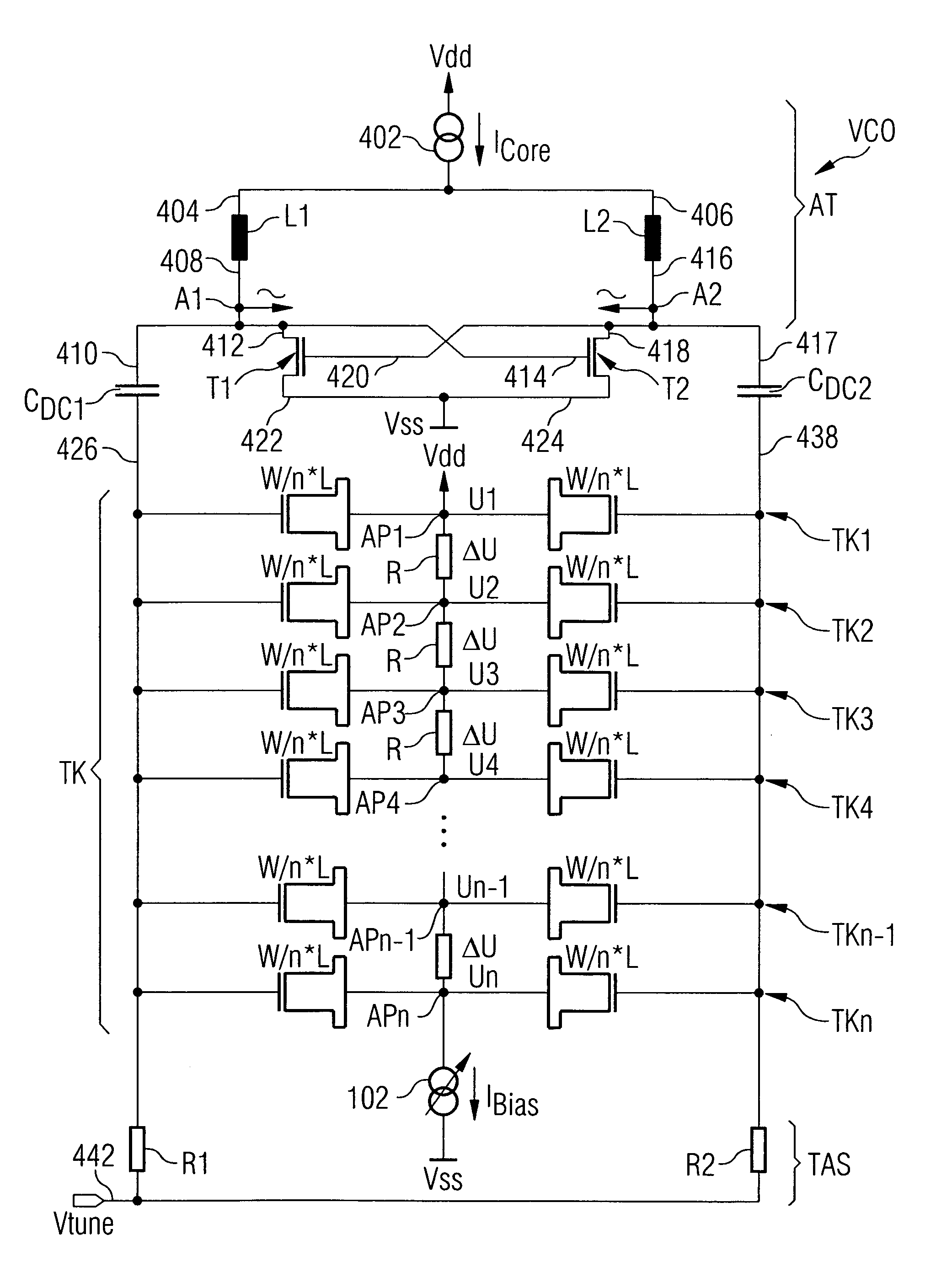
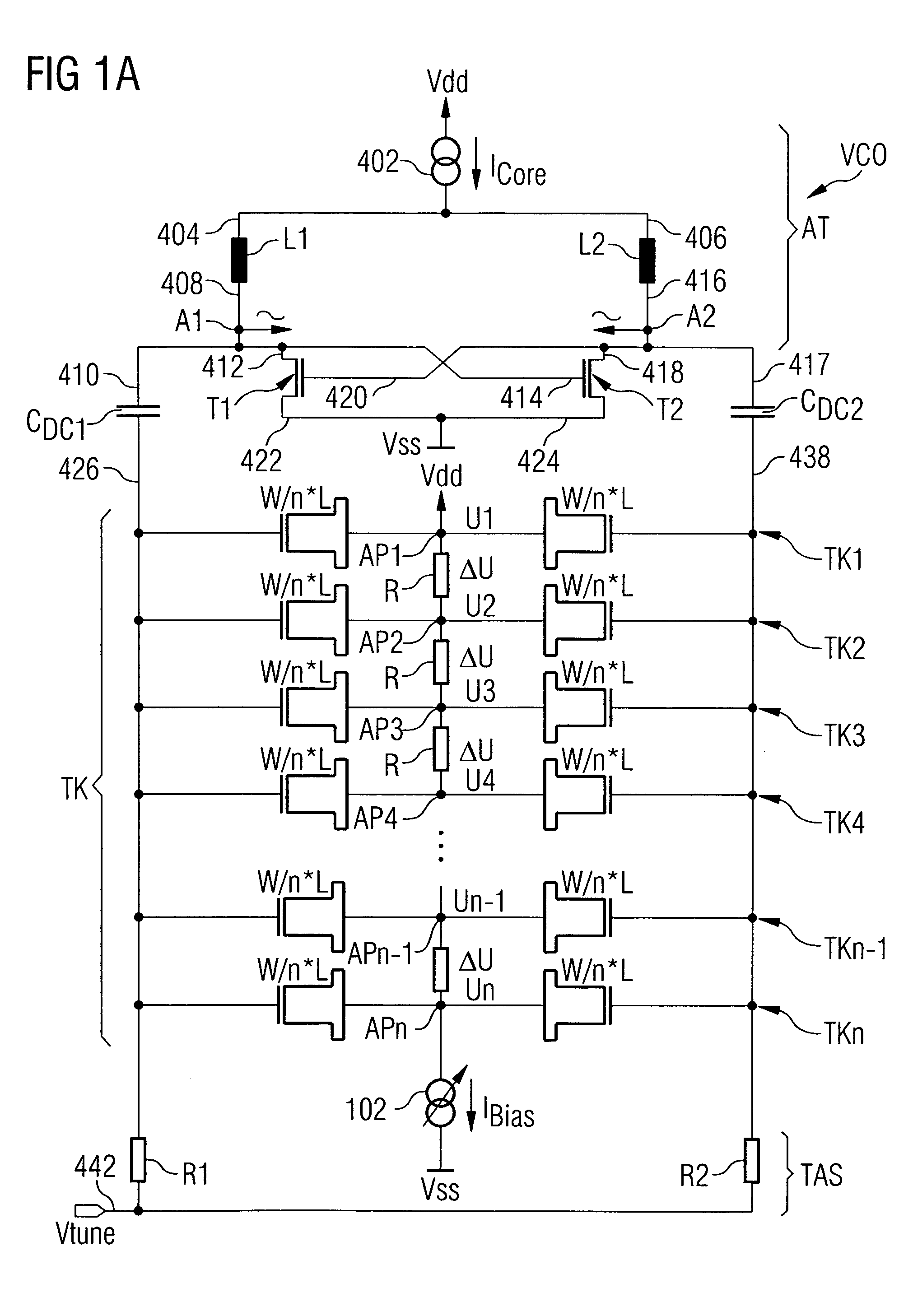
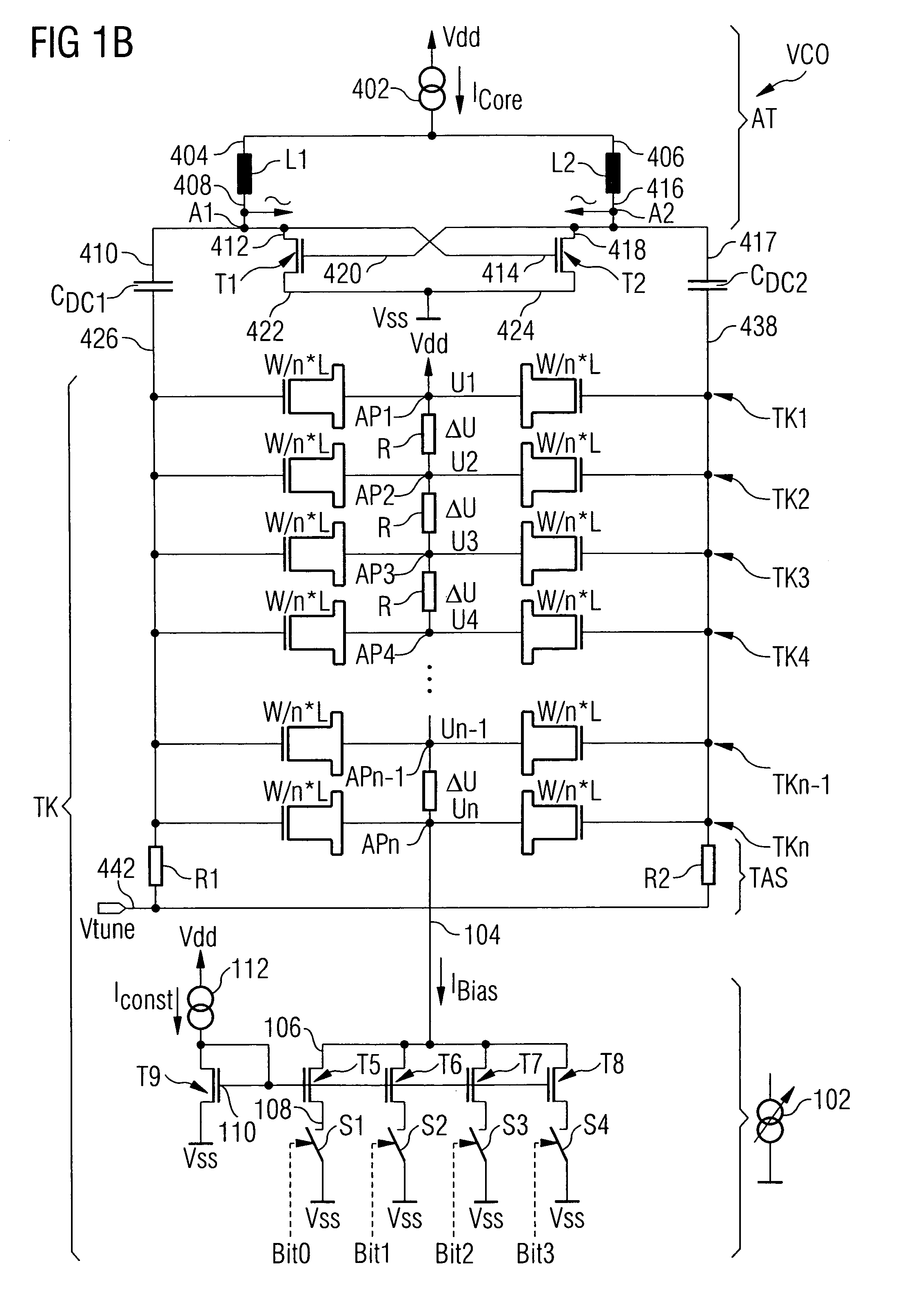
[0034]FIG. 1A shows a circuit diagram of an embodiment of the exemplary oscillator circuit. The embodiment of the exemplary oscillator circuit essentially corresponds to the conventional oscillator circuit illustrated in the circuit diagram in FIG. 4. Unlike the conventional oscillator circuit illustrated in FIG. 4, the circuit diagram of the embodiment of the exemplary oscillator circuit according to FIG. 1A shows a plurality of partial capacitances TK1, TK2, TK3, TK4, . . . , TKn−1, TKn, which, each for itself, are constructed analogously to the partial capacitance TK illustrated in FIG. 4. The individual partial capacitances thus again comprise two auxiliary transistors each whose respective drain and source terminals a...


PUM


Abstract

A circuit with variable capacitance includes a capacitance, wherein the capacitance includes a first partial capacitance and a second partial capacitance connected in parallel to the first partial capacitance, wherein a capacitance value of the first partial capacitance depends on a first bias of the partial capacitance, and a capacitance value of the second partial capacitance depends on a second bias of the second partial capacitance. The circuit with variable capacitance further includes a unit for providing the first bias and the second bias. With such a circuit with variable capacitance, it is possible to achieve a more linear and flatter characteristic tuning curve of the circuit with variable capacitance as compared to a conventional circuit with variable capacitance in a simple way.

Description

CROSS-REFERENCE TO RELATED APPLICATIONS[0001]This application claims priority from German Patent Applications No. 10 2004 008 706.7, filed on Feb. 23, 2004, and No. 10 2004 008 701.6, filed on Feb. 23, 2004, which are incorporated herein by reference in their entirety.BACKGROUND OF THE INVENTION[0002]1. Field of the Invention[0003]The present invention relates to a circuit with variable capacitance and a method for operating a circuit with variable capacitance, and, in particular, the present invention relates to an electronic circuit with variable capacitance whose transition behaviour between a minimum and a maximum saturation value is variable.[0004]2. Description of the Related Art[0005]A conventional voltage controlled oscillator (VCO) in most cases has one or more characteristic tuning curves, wherein such a characteristic curve represents the relation between an applied tuning voltage Vtune and an oscillation frequency. An exemplary oscillator circuit for a conventional volta...

Claims


Application Information

Patent Timeline
Patent Type & Authority Patents(United States)
IPC IPC(8): H03B5/12H03L7/00H03L7/099
CPCH03L7/099H03B5/1228H03B5/1293H03B5/1253H03B5/1215
Inventor KORNER, HEIKO
Owner INFINEON TECH AG
Why Eureka
Try Eureka