Micromechanical Sensor

a sensor and micro-mechanical technology, applied in the direction of turning-sensitive devices, acceleration measurement using interia forces, instruments, etc., can solve the problems of inability to linearly deflect the bend the deflection of the corresponding sensor mass becomes smaller, and the bending of the bending spring device is difficult and prone to errors, so as to reduce the stress peak in the region of turns or inflections of the spring, the bending of the bending spring devi

Active Publication Date: 2012-02-23
HANKING ELECTRONICS LTD
View PDF13 Cites 4 Cited by
  • Summary
  • Abstract
  • Description
  • Claims
  • Application Information

AI Technical Summary

Benefits of technology

[0024]When the spring bars of the double spring bar and/or the bars of the meander have a symmetrical design, uniform bending of the bending spring device in both provided directions is ensured. On the other hand, one-sided bending may be provided by an asymmetrical design of the bending spring device.
[0025]To allow particularly harmonic and uniform bending without stress peaks on individual parts of the bending spring device, it is advantageous when the meander has a radius of curvature

Problems solved by technology

However, this is not the case for the bending springs in sensors of the prior art.
Evaluation of the acting forces is therefore difficult and prone to errors.
A disadvantage of these bending spring devices of the prior art is that, for the same force, the bend of the bending spring device cannot be linearly deflected.
This is particularly disadvantageous since, for example, for the same Coriolis force the path of deflection of the corresponding sensor mass becomes smaller with increasing deflection.
This results in errors in detecting the associated acceleration or yaw rate values, or, in order to compensate for the errors, requires complicated computation

Method used


Image

  • Micromechanical Sensor
  • Micromechanical Sensor
  • Micromechanical Sensor

Examples


Embodiment Construction

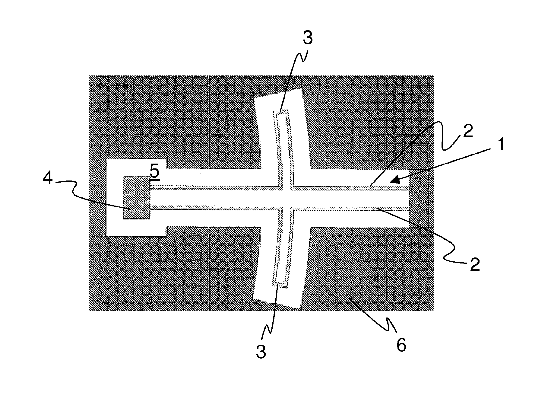
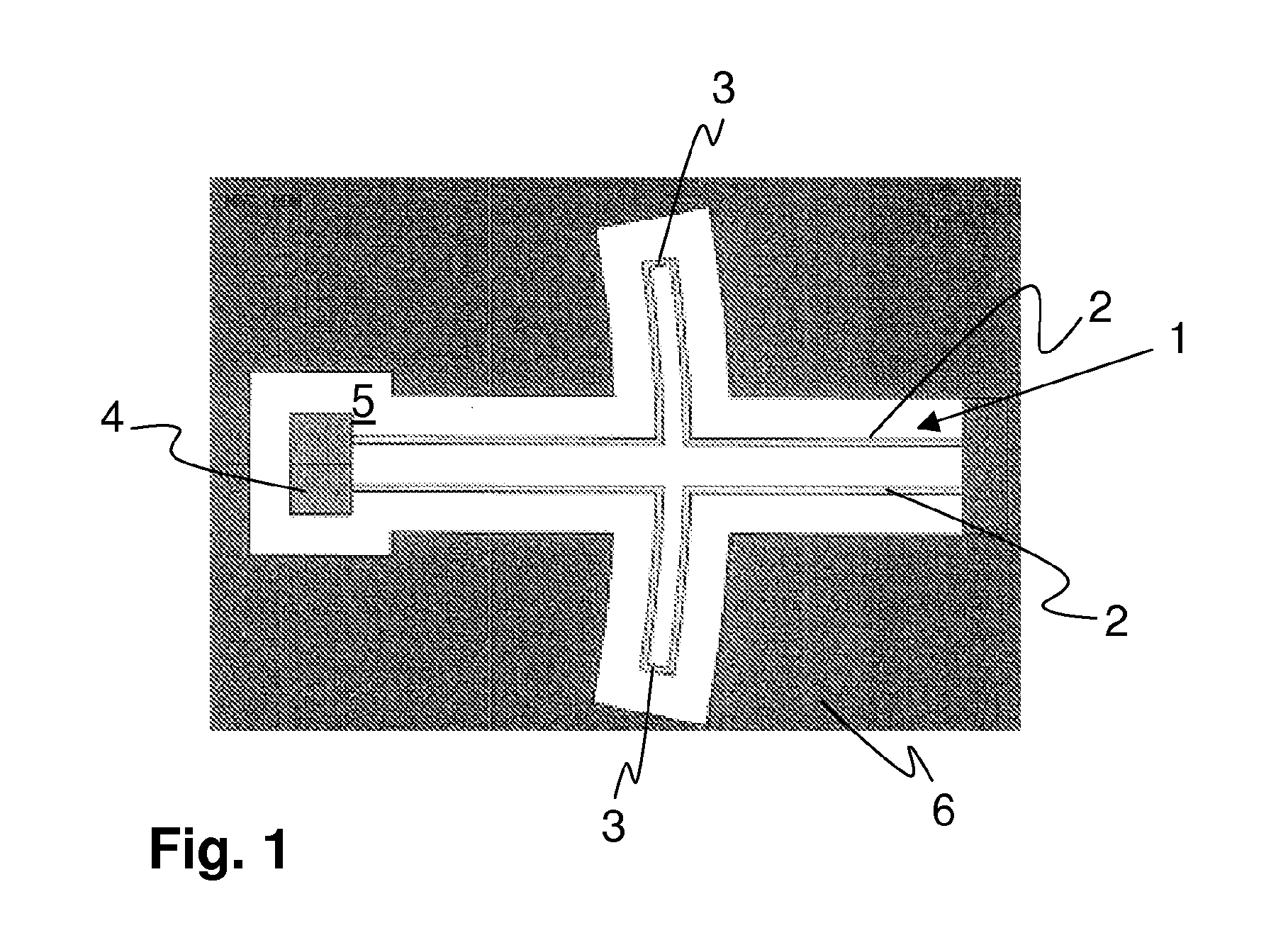
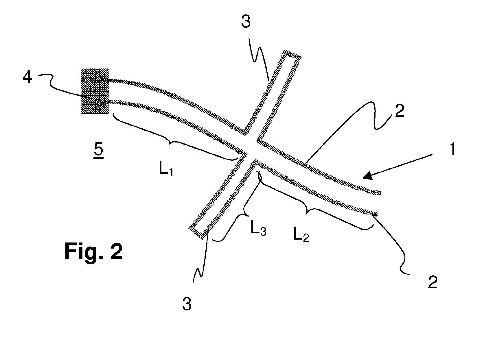
[0036]FIG. 1 shows a bending spring device 1 according to the invention, having two spring bars 2 extending parallel to one another, a meander 3 being situated on each of the spring bars 2. The bending spring device 1 is attached at one end to an anchoring 4 on a substrate 5. The other end of the bending spring device 1 is situated on a mass 6 which is deflected or bent around the anchoring 4, parallel to the substrate 5. The bending occurs in particular as primary oscillation of the mass 6 about the anchoring 4. The bending thus allows a rotational motion in a plane, or, if a sensor mass is involved, a deflection due to a Coriolis force or acceleration force which occurs. The spring bars 2 and the meander 3 have a cross-sectional design, perpendicular to the plane of the drawing, such that they allow controlled bending of the spring bars 2 and of the meander 3 in the plane of the drawing. Depending on the requirements for the mass 6, movability out of the plane of the drawing is ei...


PUM


Abstract

A micromechanical sensor comprising a substrate (5) and at least one mass (6) which is situated on the substrate (5) and which moves relative to the substrate (5) is used to detect motions of the sensor based on an acceleration force and/or Coriolis force which occur(s). The mass (6) and the substrate (5) and/or two masses which move toward one another are connected by at least one bending spring device (1) for a relative rotational motion. The bending spring device (1) has multiple, in particular two, spring bars (2) extending essentially parallel to one another for improving the linear spring characteristic of the bending spring device during the rotational motion, and at least one meander (3) on at least one, preferably on all, of the spring bars (2).

Description

CROSS REFERENCE TO RELATED PATENT APPLICATIONS[0001]This application is the National Phase Application under 35 USC§371 of International Application No. PCT / EP2010 / 055635, filed Apr. 27, 2010, which claims priority to German Patent Application 10 2009 002 701.7, filed Apr. 28, 2009.BACKGROUND[0002]A. Technical Field[0003]The present invention relates to a micromechanical sensor comprising a substrate and at least one mass which is situated on the substrate and which moves relative to the substrate for detecting motions of the sensor based on an acceleration force and / or Coriolis force which occur(s), the mass and the substrate and / or two masses which move toward one another being connected by at least one bending spring device for a relative rotational motion.[0004]B. Background of the Invention[0005]Micromechanical sensors are used for detecting accelerations and / or yaw rates along a spatial axis or at least one of three mutually orthogonal spatial axes. The operating principle is ...

Claims


Application Information

Patent Timeline
IPC IPC(8): G01C19/56G01C19/5712
CPCB81B3/007B81B2201/0235B81B2203/0118G01P2015/0817G01C19/5712G01P15/08B81B2203/056
Inventor HAMMER, HANNO
Owner HANKING ELECTRONICS LTD
Why Eureka
Try Eureka