High spur-free dynamic range receiver

Active Publication Date: 2012-01-10
LOCKHEED MARTIN CORP
View PDF2 Cites 4 Cited by
  • Summary
  • Abstract
  • Description
  • Claims
  • Application Information

AI Technical Summary

Benefits of technology

[0005]Various embodiments of the present invention solve the foregoing problems by providing a receiver with high spur-free dynamic range (“SFDR”). The receiver includes one or more tunable filters, each of which includes one or more electro-optic resonators. These resonators, which operate in a whispering-gallery mode (“WGM”), can be rapidly tunable and provide precise, narrow bandwidth filtering for separating signals of interest and for suppressing interference from frequencies adjacent to those signals of interest. The receiver further includes

Problems solved by technology

Many receivers, however, are unable to selectively filter interfering signals with sufficient pe

Method used


Image

  • High spur-free dynamic range receiver
  • High spur-free dynamic range receiver
  • High spur-free dynamic range receiver

Examples


Example

[0019]In the following detailed description, numerous specific details are set forth to provide a full understanding of the present invention. It will be apparent, however, to one ordinarily skilled in the art that the present invention may be practiced without some of these specific details. In other instances, well-known structures and techniques have not been shown in detail to avoid unnecessarily obscuring the present invention.

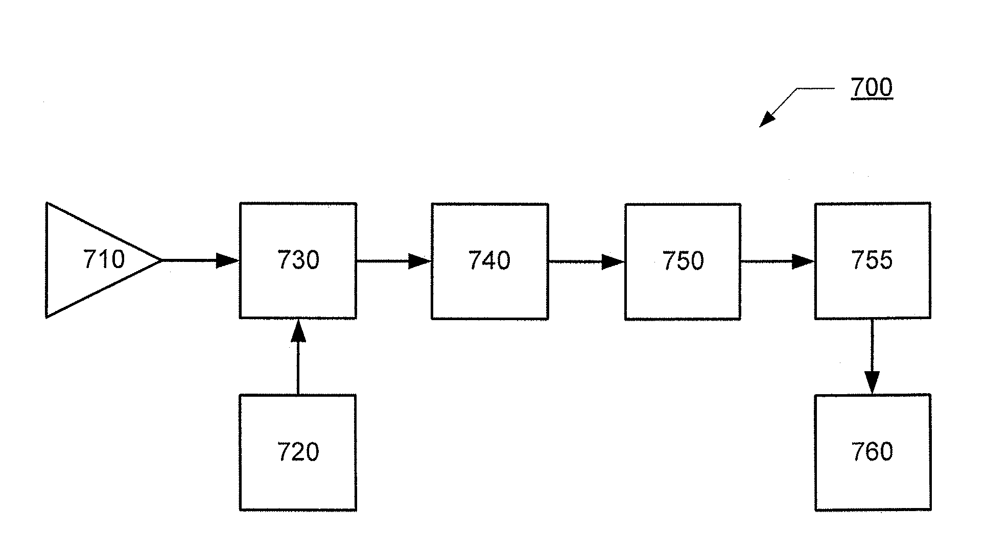
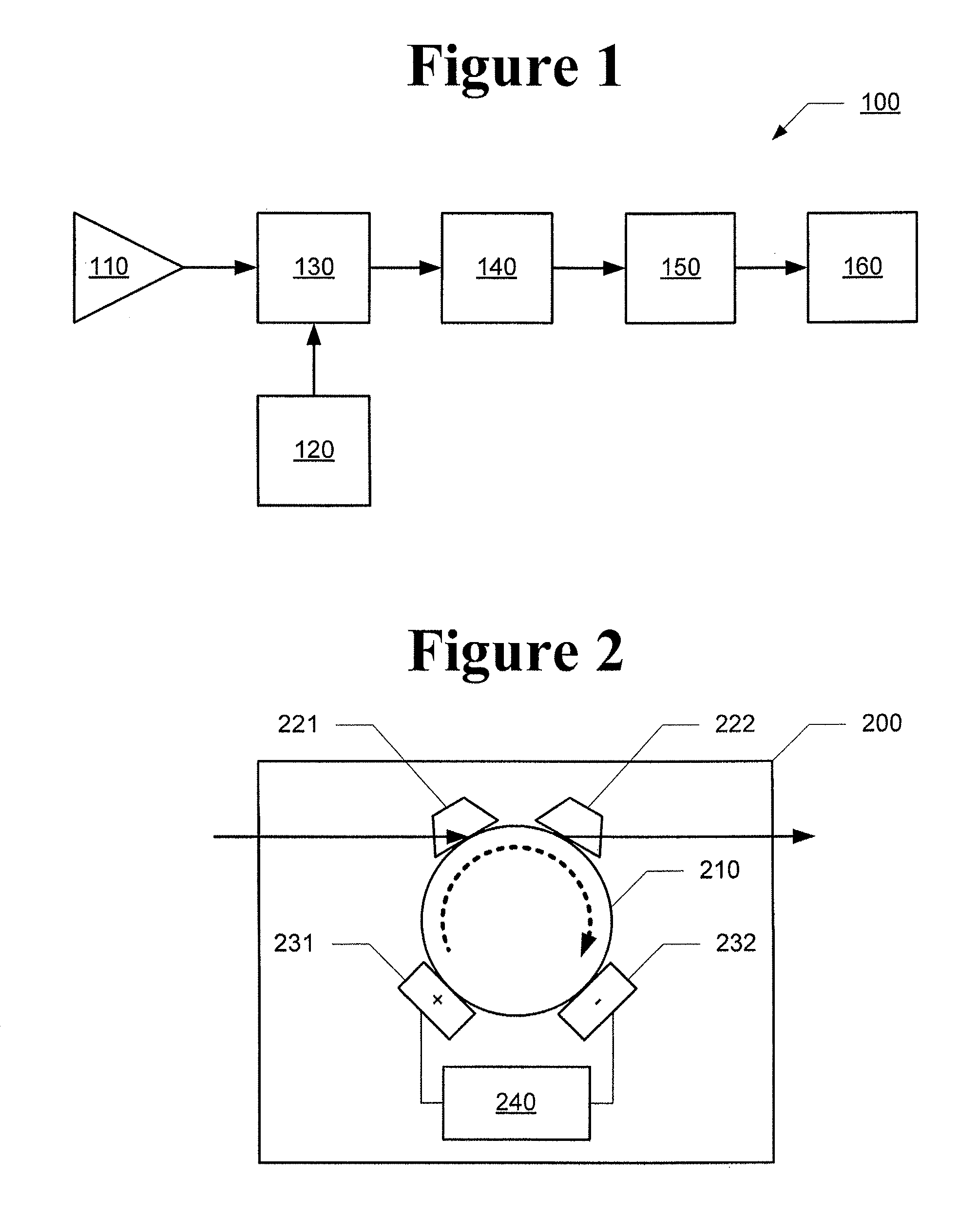
[0020]FIG. 1 illustrates a block diagram of a high spur-free dynamic range (“SFDR”) receiver in accordance with one embodiment of the present invention. The high SFDR receiver 100 includes an antenna 110 that receives an incoming RF signal. The RF signal is modulated onto an optical carrier, produced by laser 120, in modulator 130. In accordance with various aspects of the present invention, modulator 130 may be an electro-absorption modulator (“EAM”), a Mach Zehnder interferometer (“MZI”), or the like. The output optical signal from modulator 130 is prov...


PUM


Abstract

A receiver system comprises an antenna configured to receive an input RF signal, a high spur free dynamic range modulator configured to receive the input RF signal from the antenna and to convert the input RF signal to an optical signal, and a tunable filter configured to receive the optical signal and to output a filtered optical signal. The tunable filter includes at least one electro-optic resonator, at least one electrode configured to supply an electrical control signal to the electro-optic resonator, and a controller configured to adjust the electrical control signal to adjust a refractive index of the electro-optic resonator, whereby a resonant frequency of the electro-optic resonator is selectably adjusted. The receiver system further comprises a receiver configured to receive the filtered optical signal.

Description

CROSS-REFERENCE TO RELATED APPLICATION[0001]Not applicable.STATEMENT REGARDING FEDERALLY SPONSORED RESEARCH OR DEVELOPMENT[0002]Not applicable.FIELD OF THE INVENTION[0003]The present invention generally relates to receivers and, in particular, relates to high spur-free dynamic-range (“SFDR”) receivers.BACKGROUND OF THE INVENTION[0004]To receive radio frequency (“RF”) signals with a sufficient signal-to-noise ratio “SNR,” it is frequently necessary to selectively filter interfering signals in frequency bands adjacent to the RF signal of interest. Many receivers, however, are unable to selectively filter interfering signals with sufficient performance, particularly rapid tunability, to utilize the RF signal in high-bandwidth operations.SUMMARY OF THE INVENTION[0005]Various embodiments of the present invention solve the foregoing problems by providing a receiver with high spur-free dynamic range (“SFDR”). The receiver includes one or more tunable filters, each of which includes one or ...

Claims


Application Information

Patent Timeline
IPC IPC(8): H04B10/00
CPCH04B10/25759H04B2210/006
Inventor KARRAS, THOMAS W.KOWALCZYK, ANTHONY C.
Owner LOCKHEED MARTIN CORP
Why Eureka
Try Eureka