Tunable filter devices and methods

Active Publication Date: 2014-07-17
PHYSICAL DEVICES
View PDF6 Cites 10 Cited by
  • Summary
  • Abstract
  • Description
  • Claims
  • Application Information

AI Technical Summary

Benefits of technology

[0010]The first object of the invention is to provide better utilization of RF spectrum. The second object is to provide a tunable filter for RF signals. The third object is to provide a band-passed signal output having a tunable center frequency and/or pass-band band

Problems solved by technology

As a result, the number of filters integrated in a smart phone is growing rapidly, increasing the cost, complexity and space burden imposed by the filters.
Without a w

Method used


Image

  • Tunable filter devices and methods
  • Tunable filter devices and methods
  • Tunable filter devices and methods

Examples


Example

[0032]Unless defined otherwise, terms are used herein according to their generally accepted engineering definitions. Although described in terms of signal reception, filter can be used in signal transmission. Although described in terms of RE electrical signals, this disclosure is intended to cover electrical and electromagnetic signals of any frequency as well as other physical signals including radar, light, and sound among others. The device, herein after referred to as a filter, can comprise any circuit type, such as electrical, electronic, optoelectronic, complementary metallic- oxide semiconductor or other.

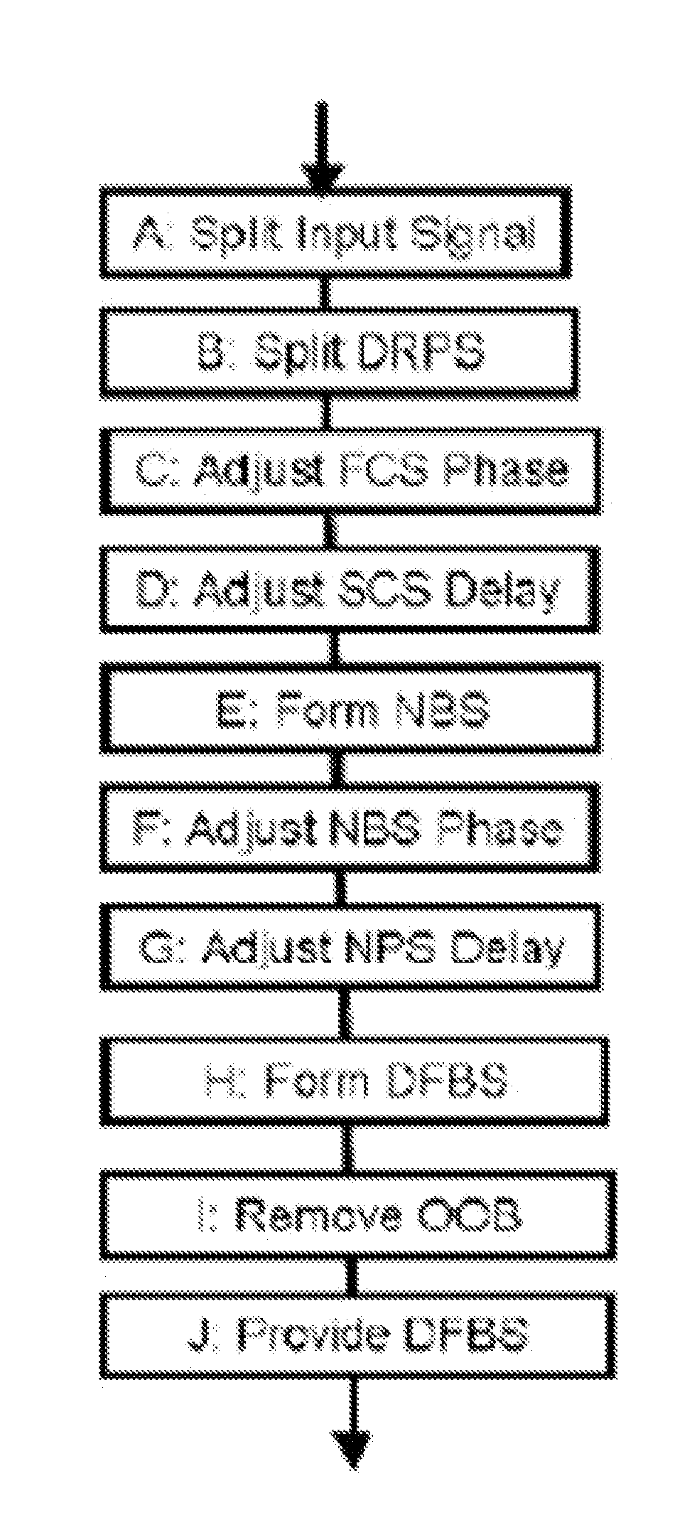
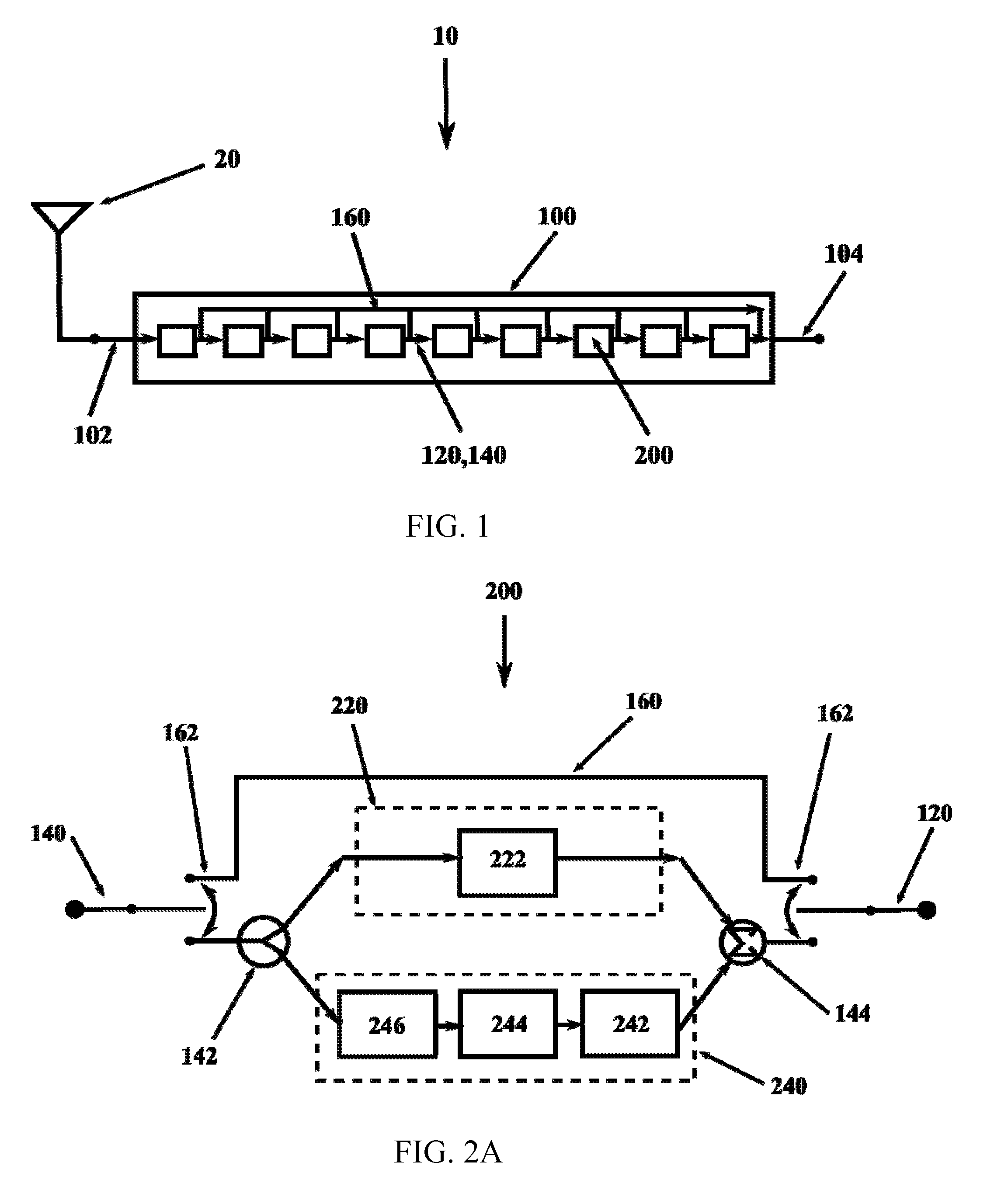
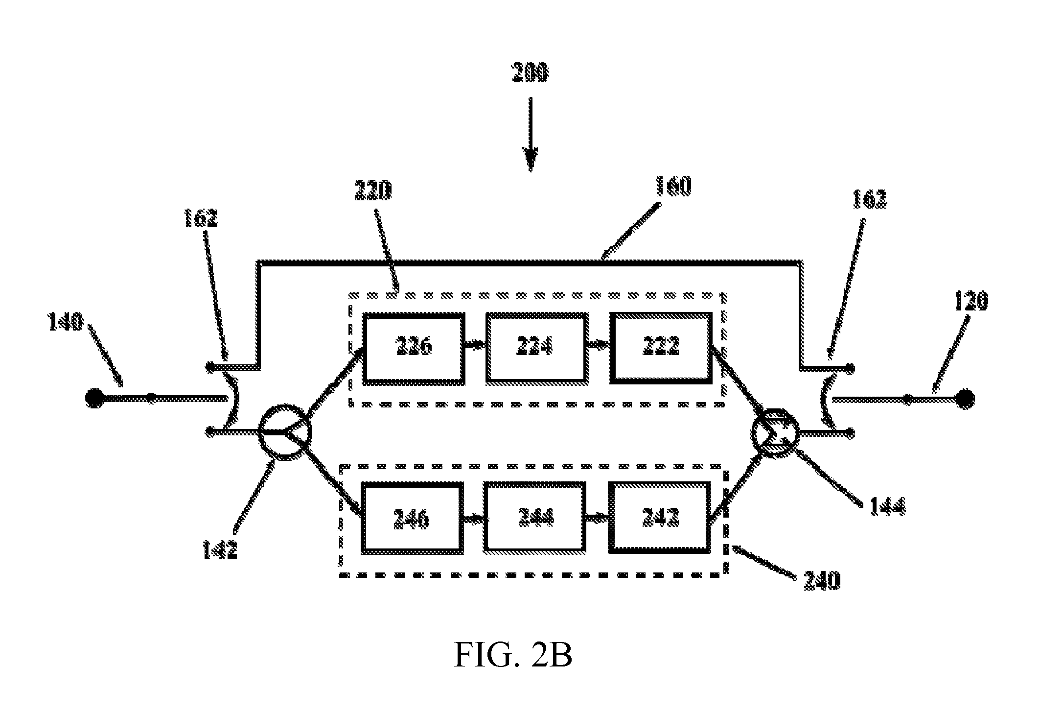
[0033]Although the filter is illustrated here as a series configuration, parallel and mixed parallel and series configurations are acceptable. For purposes of this disclosure, configuring is intended to include tuning and connections of cells and / or units. It should also be noted that steps of configuring, e g tuning, are mathematically associative and commutative and, there...


PUM


Abstract

Analog interference filter devices and methods for isolation of desirable portions of a radio frequency signal. Signal compensation is used to provide desirable center frequency, passband width, ripple, rolloff, stopband and distortion performance. The filter is implemented with passive and/or active components.

Description

CROSS-REFERENCE TO RELATED APPLICATIONS[0001]The present application claims the benefit of the filing date of U.S. Provisional Patent Application Ser. No. 61 / 402,416 filed by the present inventor on Aug. 30, 2010 and U.S. Provisional Patent Application Ser. No. 61 / 510,330 filed by the present inventor on Jul. 21, 2011.[0002]The aforementioned provisional patent applications are hereby incorporated by reference in their entirety.STATEMENT REGARDING FEDERALLY SPONSORED RESEARCH OR DEVELOPMENT[0003]None.BACKGROUND OF THE INVENTION[0004]1. Field of The Invention[0005]This invention relates to radio frequency communication. More specifically, it relates to tuning of devices to selectively receive desired signals.[0006]2. Brief Description of the Related Art[0007]Consumer demand for wireless connectivity by smart phones, pads and notebook computers (“smart phones”) is exploding, with national demand expected to exceed capacity by 2013. In response, the federal government is expanding the ...

Claims


Application Information

Patent Timeline
IPC IPC(8): H04B1/12
CPCH04B1/12H03H7/46H03H11/34H03H2210/012H03H2250/00H04B1/123H03H11/0405
Inventor WILKERSON, JONATHAN RYAN
Owner PHYSICAL DEVICES
Why Eureka
Try Eureka