Electromagnetic vibration exciter system with adjustable electro-viscoelastic suspension device

Active Publication Date: 2013-09-12
ZHEJIANG UNIV +1
View PDF5 Cites 2 Cited by
  • Summary
  • Abstract
  • Description
  • Claims
  • Application Information

AI Technical Summary

Benefits of technology

The present invention provides a novel electromagnetic vibration exciter system with an adjustable electro-viscoelastic suspension device. This device can adjust its stiffness and damping parameters easily to improve the performance of the novel electromagnetic exciter. The system has excellent linear quality even for a long-stroke vibration. The transfer function of the exciter system applying the electro-viscoelastic suspension device changes to be a typical single-degree-of-freedom model. The equivalent damping and stiffness can be adjusted through the adjustment of the gain of the adjustable amplifier, the adjustable phase shifter and the proportioner. This invention has the advantage of parameter adjustable, linear and convenience.

Problems solved by technology

Besides, the larger the displacement amplitude of the exciter is, the smaller the stiffness of the mechanical elastic suspension device should be.
However, in order to reduce the effect of the zero drift of the moving component and the environmental noise, the dampness of the suspension device should be relatively large.
It is difficult to design such type of mechanical elastic suspension device with small stiffness and large dampness.
In addition, due to that the material characteristics of the mechanical elastic suspension device change always with time, the positional accuracy cannot be repeatable.
Finally, when the installation of the mechanical elastic suspension device is finished, its stiffness and damping parameters cannot be modified freely any more.
For these reasons, the mechanical elastic suspension device cannot meet the requirement arisen with the continuous development of electromagnetic exciters, especially for the long-stroke electromagnetic exciter.

Method used


Image

  • Electromagnetic vibration exciter system with adjustable electro-viscoelastic suspension device
  • Electromagnetic vibration exciter system with adjustable electro-viscoelastic suspension device
  • Electromagnetic vibration exciter system with adjustable electro-viscoelastic suspension device

Examples


Embodiment Construction

[0027]Hereinafter, embodiments of the present invention will be described with reference to the accompanying drawings.

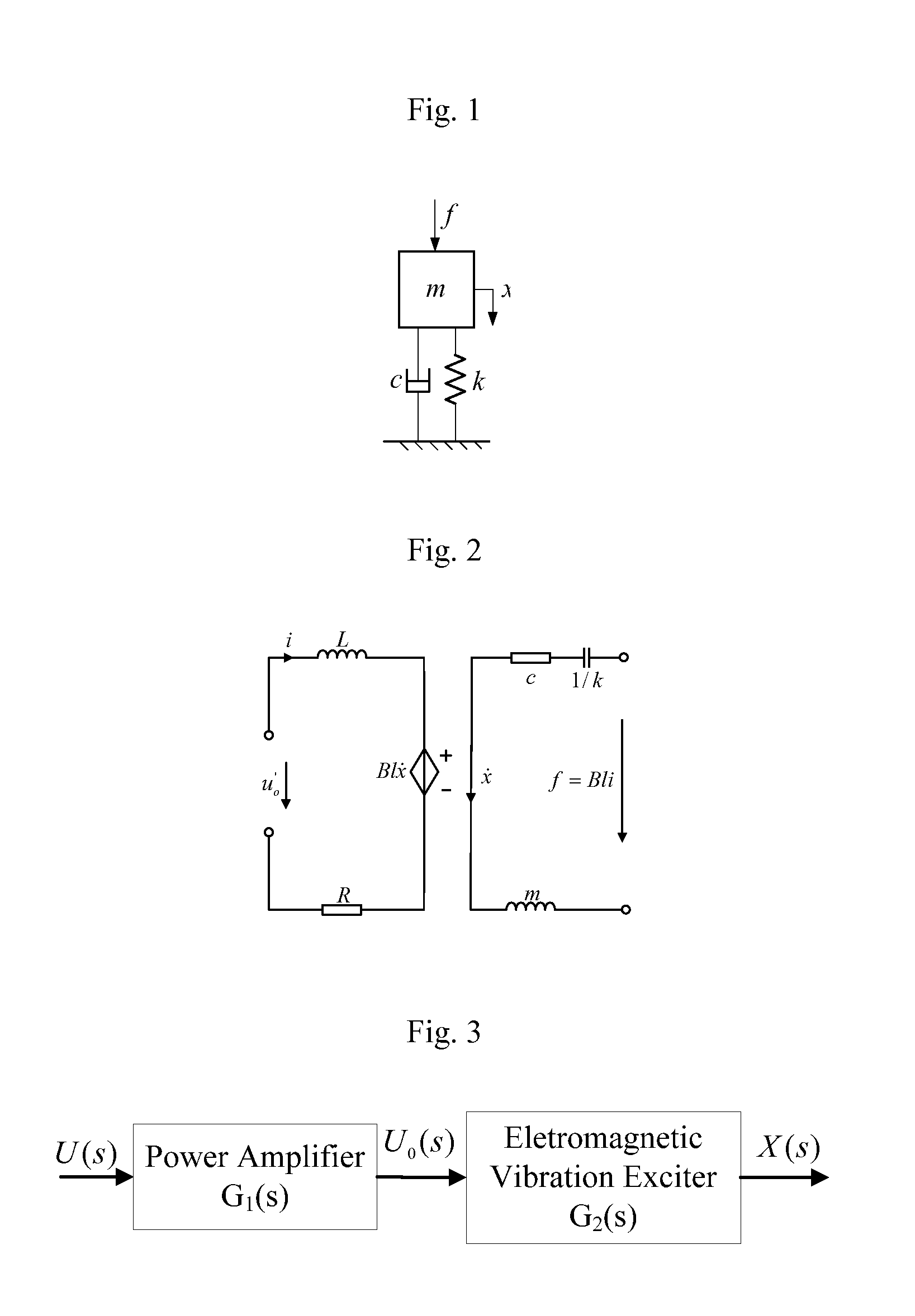
[0028]The electromagnetic vibration exciter system with an adjustable electro-viscoelastic suspension device comprises an electromagnetic vibration exciter and a power amplifier.

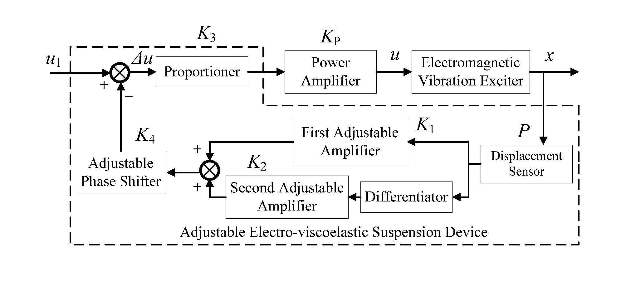
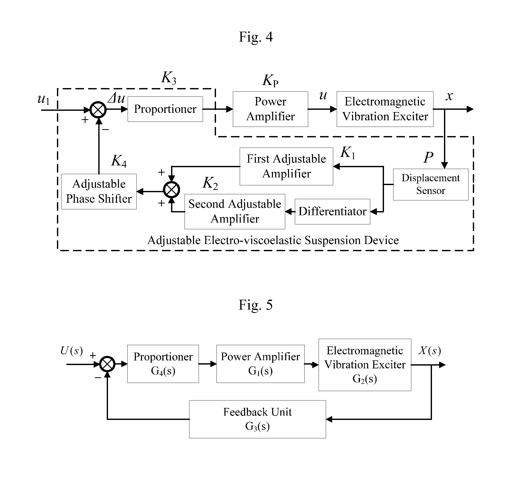
[0029]The adjustable electro-viscoelastic suspension device is adopted in the vibration exciter system to support and restore its moving component and comprises a displacement sensor detecting the displacement of the moving component of the electromagnetic exciter, a first adjustable amplifier, a second adjustable amplifier, a differentiator, an adder and an adjustable phase shifter, a subtracter, a proportioner.

[0030]The displacement signal detected by the sensor is processed by the first adjustable amplifier and a first amplified signal is produced. The displacement signal is simultaneously processed by the differentiator and the second adjustable amplifier successively and a second amplifi...


PUM


Abstract

The electromagnetic vibration exciter system with an adjustable electro-viscoelastic suspension device comprises an electromagnetic vibration exciter, a power amplifier and an adjustable electro-viscoelastic suspension device, which acts as the suspension device of the electromagnetic vibration exciter. The adjustable electro-viscoelastic suspension device contains a displacement sensor detecting the displacement of the moving component, a first adjustable amplifier and a second adjustable amplifier, a differentiator, an adjustable phase shifter, an adder and a proportioner. The linearity of the stiffness and damping of the exciter system is excellent, which can be adjusted as need through the adjustment of gain of the adjustable amplifier, the proportioner, the adjustable phase shifter. This invention has adjustable and linear parameters and it is also easy to be realized.

Description

FIELD OF THE INVENTION[0001]This present invention relates to an electromagnetic vibration exciter system with an adjustable electro-viscoelastic suspension device.BACKGROUND OF THE INVENTION[0002]The electromagnetic vibration exciter usually comprises a fixed base, a magnetic circuit, a moving component, a guiding device, a suspension system and so on. With the development of the science and technology, the electromagnetic exciters are constantly required to output a vibration signal with a larger and larger displacement amplitude. For example, at a low frequency or even an ultralow frequency, the exciter should output a vibration signal with the displacement amplitude of 1000 mm in order to obtain a large signal-to-noise ratio. The long-stroke vibration exciter raises new requirement for the property of the elastic suspension device.[0003]An electromagnetic vibration exciter generally uses mechanical elastic suspension devices, such as metal spring leaf or rubber tubes, etc. to su...

Claims


Application Information

Patent Timeline
IPC IPC(8): H02P6/00H02P6/16
CPCH02P6/001G01M7/022H02P6/16H02P6/34
Inventor HE, WENWANG, CHUNYUSHEN, RUNJIEJIA, SHUSHIYU, MEIMA, MINGDE
Owner ZHEJIANG UNIV
Why Eureka
Try Eureka