Positioning system

a positioning system and positioning technology, applied in direction finders using radio waves, measurement devices, instruments, etc., can solve the problems of large hardware investment, extremely weak signals, and virtually non-existent signals,

Active Publication Date: 2007-01-30
U-BLOX
View PDF17 Cites 18 Cited by
  • Summary
  • Abstract
  • Description
  • Claims
  • Application Information

AI Technical Summary

Benefits of technology

[0004]It is an object of the invention to provide a system of the generic type which is simple and, in particular, does not require central administration of the transmit antennas or synchronisation of the receiver.

Problems solved by technology

Often the position of a receiver must be determined in places where the sources of primary positioning signals as emitted by, in particular, satellites are obscured from view and, as a consequence, the signals are extremely weak or virtually non-existent, e.g., in woods, buildings, mines etc.
The system is relatively complicated and requires expensive hardware.

Method used


Image

  • Positioning system
  • Positioning system
  • Positioning system

Examples


Embodiment Construction

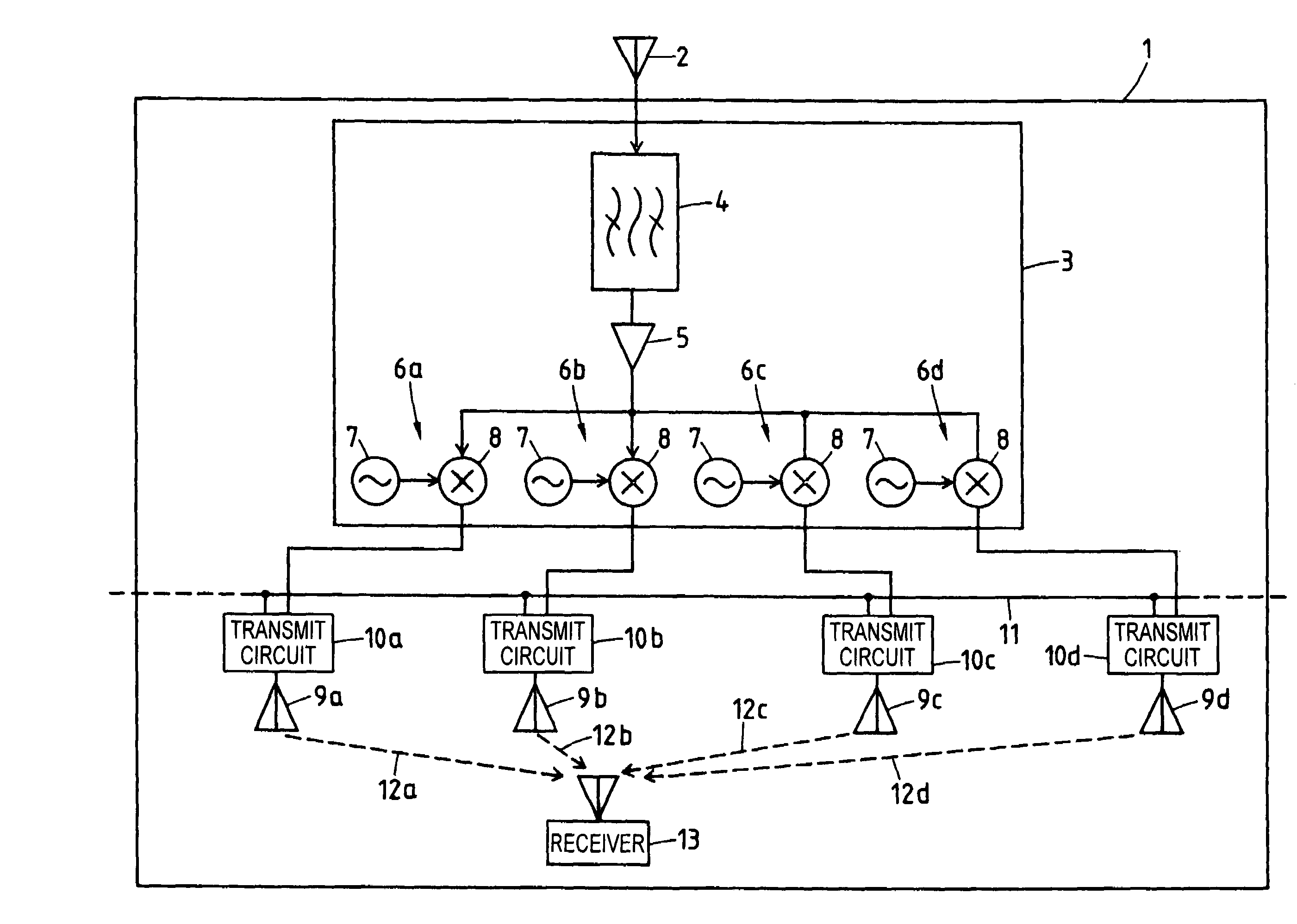
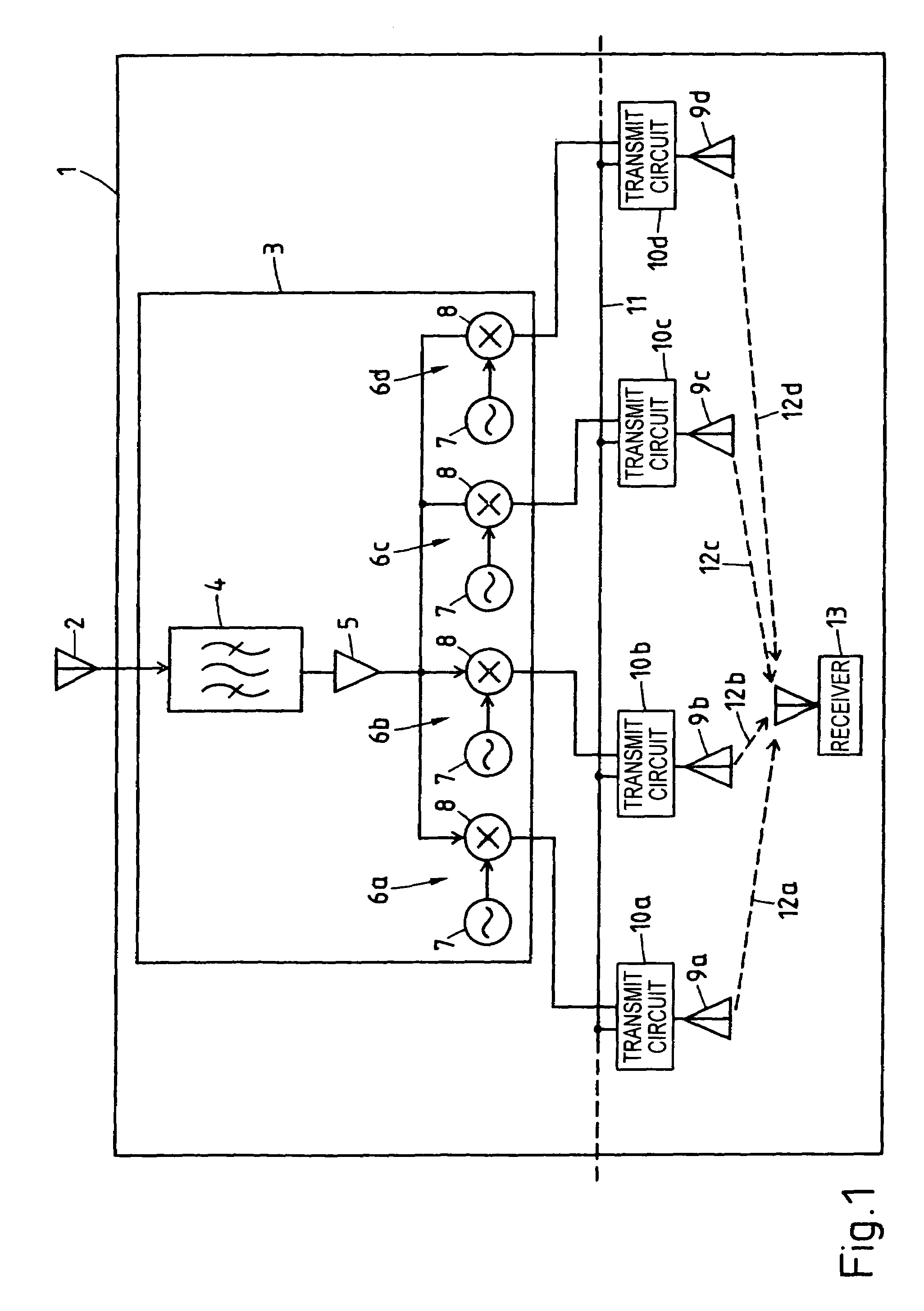
[0010]On the roof of a building 1 a receive antenna 2 for receiving primary positioning signals which usually stem from GPS satellites but may in part come from pseudolites and similar devices as well, is mounted. It is connected by an RF cable to a repeater 3 which comprises a bandpass filter 4 and a low noise amplifier 5 whose output is connected to four parallel conversion circuits 6a–d. Each of the conversion circuits 6a–d comprises an oscillator 7 for producing a sine-shaped conversion signal with a specific fixed frequency and a mixer 8 for mixing the same with the output signal of low noise amplifier 5.

[0011]The outputs of conversion circuits 6a–d are each connected by an RF cable to one of transmit antennas 9a;b;c;d which are mounted at fixed locations inside building 1, via one of transmit circuits 10a;b;c;d. Each of the latter contains an interface connecting it to a LAN cable 11 and is capable of converting data received via the same into 802.11 WLAN format and vice versa...


PUM


Abstract

For allowing positioning of a GPS receiver within a building, GPS primary positioning signals received by an outdoor receive antenna are up-converted to different carrier frequencies in the 2.4 GHz ISM band and the converted signals are transmitted each by a transmit antenna inside the building, the transmit antennas serving at the same time as access points of a WLAN which is used for transmitting additional positioning data like the positions of the transmit antennas and the signal delay times associated with them. By cycling through the secondary positioning signals received from the transmit antennas, i.e., down-converting each of them during an assigned time slot, and determining clock bias differences in the receiver, the position of the latter is determined using TDOA algorithms.

Description

FIELD OF THE INVENTION[0001]The invention concerns a positioning system where a receiver uses signals emitted by satellites, pseudolites and similar in order to determine its position. Well-known systems of this type are the GPS system and the GLONASS system.PRIOR ART[0002]Often the position of a receiver must be determined in places where the sources of primary positioning signals as emitted by, in particular, satellites are obscured from view and, as a consequence, the signals are extremely weak or virtually non-existent, e.g., in woods, buildings, mines etc. Several methods have been developed to allow positioning under such circumstances. In known systems of the generic type (see G. -I. Jee et al., ‘Indoor Positioning using TDOA Measurements from Switching GPS Repeater’, ION GNSS 2004, pp. 1970–1976 or J. Caratori et al., ‘UPGRADE RnS Indoor Positioning System in an Office Building’, ION GNSS 2004, pp. 1959–1969) several secondary positioning signals are produced and each of the...

Claims


Application Information

Patent Timeline
Patent Type & Authority Patents(United States)
IPC IPC(8): G01S1/00G01S19/11
CPCG01S19/11G01S5/10
Inventor THIEL, ANDREASMATHIS, HEINZFAVEY, ETIENNE
Owner U-BLOX
Why Eureka
Try Eureka