
Methods and apparatus for sub-harmonic generation, stereo expansion and distortion

a sub-harmonic frequency and stereo expansion technology, applied in the direction of stereophonic systems, electrical apparatus, stereophonic arrangments, etc., can solve the problems of poor attack, “rumbly” sound, and the energy of the output signal in the sub-harmonic frequency range does not exhibit desirable amplitude characteristics, so as to improve the sound of a kick-drum, the effect of improving the sound or synthesizing the sound

Inactive Publication Date: 2007-01-30
PEAVEY ELECTRONICS
View PDF21 Cites 10 Cited by
  • Summary
  • Abstract
  • Description
  • Claims
  • Application Information

AI Technical Summary

Benefits of technology

[0006]The present invention provides improvements over existing sub-harmonic generators and achieves further functionality in its sub-harmonic generator, such as providing adjustability (preferably user adjustability) of the sub-harmonic amplitude envelope. Indeed, it has been found that this can result in highly enjoyable sound characteristics. For example, a percussive attack effect can be achieved when the rate of attack or decay of the amplitude envelope of the sub-harmonic signal is increased, which effect can improve (or synthesize) the sound of a kick-drum or the like. It has also been found to be desirable to modify the energy level of the amplitude envelope of the sub-harmonic signal under certain circumstances, such as when the rates of sloping portions of the amplitude envelope of the sub-harmonic signal are increased. Indeed, in that case, increasing the energy level of the amplitude envelope would tend to balance an apparent decrease in the energy level of the amplitude envelope resulting from a faster slope. In an alternative situation, where the rates of the sloping portions of the amplitude envelope have been reduced, it has been found that a desirable balance in the energy level of the amplitude envelope results when such energy level is reduced.
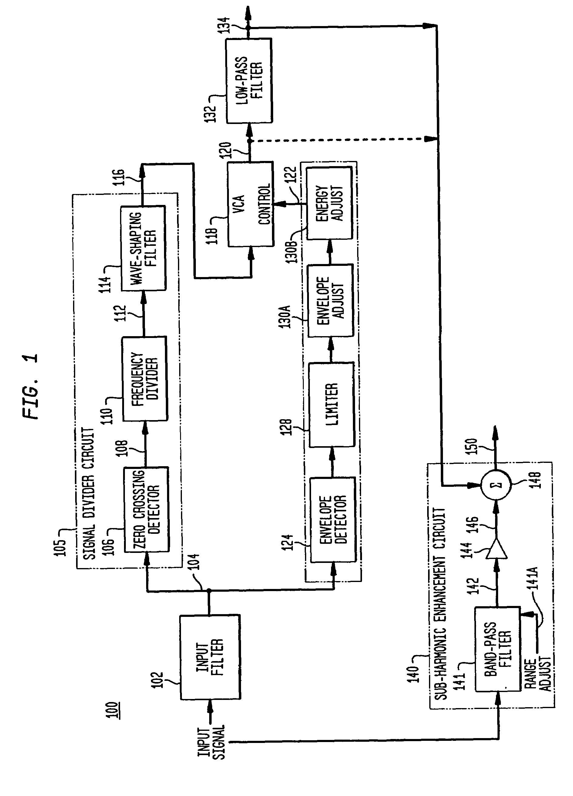
[0007]The present invention still further provides for enhancing the sub-harmonic effect by enabling an adjustment (preferably a user adjustment) in the frequency characteristics of a sub-woofer audio signal, which signal is aggregated with the sub-harmonic signal.
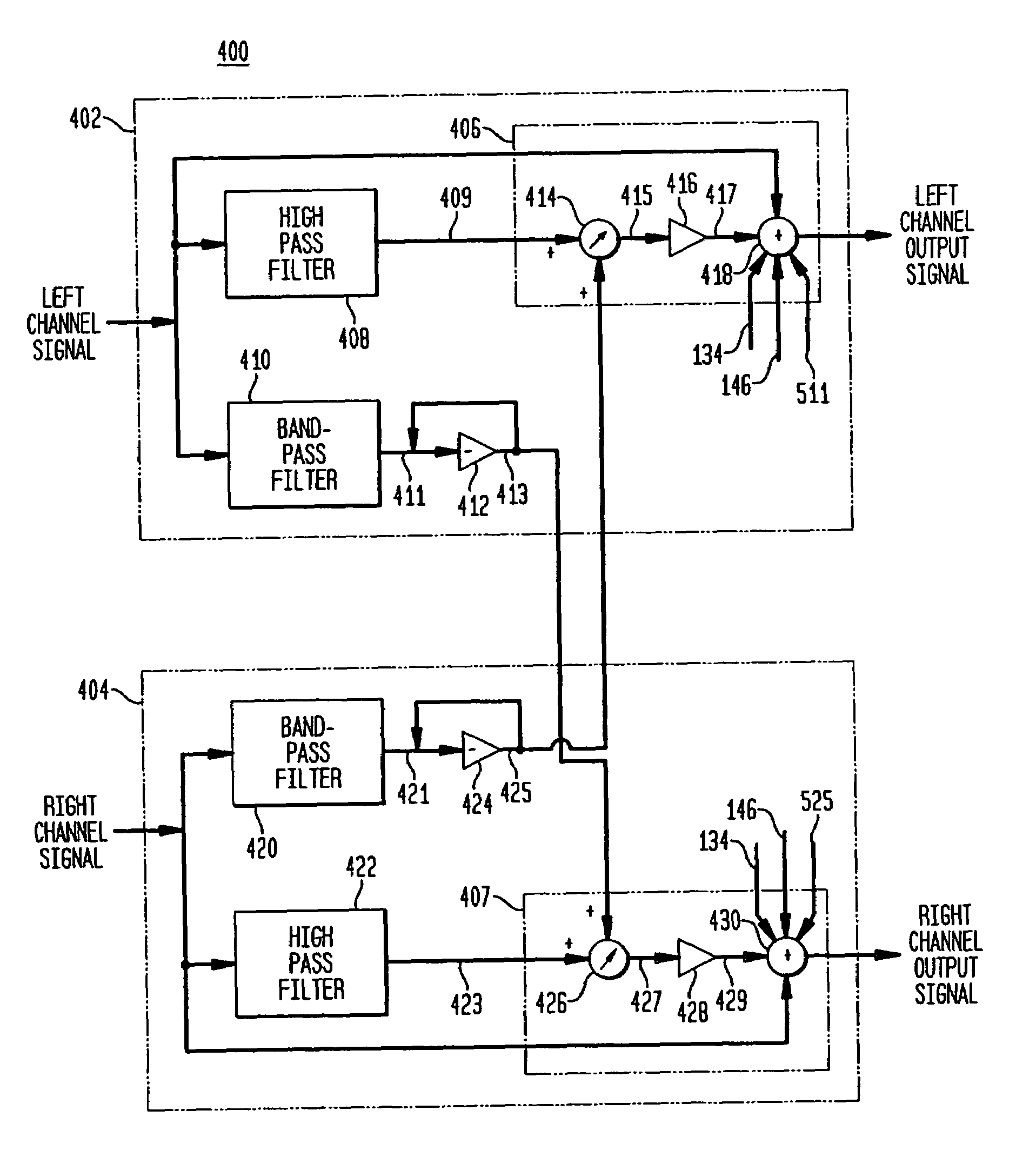
[0008]The present invention also provides for adjustability in an amount of stereo width expansion produced by left and right channels of a stereo system. More particularly, in accordance with the present invention, it has been discovered that desirable sound characteristics are achieved when a balance between the amount of stereo width expansion and an amount of high frequency boost is made adjustable (preferably user adjustable) in each of the left and right channels. This advantageously permits a user to adjust this balance to achieve overtones, timbre, etc. that complement the character of the audio content.
[0009]The present invention further provides for introducing an acoustic brightness into the audio content, preferably into both the left and right channels of a stereo signal. More particularly, the present invention provides for aggregating an adjustable level (preferably user adjustable) of additional harmonic frequency content to the left and right channels, which frequency content emulates the higher frequency distortion effects of a vacuum tube amplifier. Advantageously, the present invention contemplates offsetting frequency characteristics of the added harmonic frequency content provided in the left and right channels of the audio content to increase and / or complement the stereo width expansion effect.

Problems solved by technology

In practice, however, the audible characteristics of the output signal from conventional sub-harmonic generators suffer from a number of disadvantages, namely (i) a relatively flat (or “cardboard”) audible sound is obtained from the output signal due primarily to the increase in energy from sub-harmonic frequency components without modifying other frequency characteristics of the input signal, this disadvantage may also manifest in a “rumbly” sound depending on the frequency content of the input signal; and (ii) the audible sound exhibits poor “attack” and “decay” characteristics due to an inability by the sub-harmonic generator to accurately reflect an amplitude envelope of the input signal as a function of the frequency components of interest.
Thus, the energy of the output signal in the sub-harmonic frequency range does not exhibit desirable amplitude characteristics.
In addition, conventional sub-harmonic generators have not effectively utilized sub-harmonic signals in stereo applications, particularly where maintaining stereo “width” is of importance.

Method used


Image

  • Methods and apparatus for sub-harmonic generation, stereo expansion and distortion
  • Methods and apparatus for sub-harmonic generation, stereo expansion and distortion
  • Methods and apparatus for sub-harmonic generation, stereo expansion and distortion

Examples


Embodiment Construction

[0032]Turning now to the drawings wherein like numerals indicate like elements, there is shown in FIG. 1 a block diagram of a sub-harmonic generator 100 in accordance with one or more aspects of the present invention. It is noted that for the sake of clarity and brevity the block diagram of FIG. 1 will be discussed as being directed to an apparatus 100. It is understood, however, that the block diagram has equal applicability as to the description of one or more methods where the actions thereof correspond to the functionality of the illustrated blocks. The sub-harmonic generator 100 includes an input filter 102, a signal divider 105, a voltage controlled amplifier 118, and a gain control 123. Further embodiments of the sub-harmonic generator 100 may also include a low pass filter 132, a sub-harmonic enhancement 140, which preferably includes at least one adjustable band-pass filter 141, an amplifier 144 and a summing function 148.

[0033]The input filter 102 is preferably operable to...


PUM


Abstract

Methods and apparatus are disclosed that achieve sub-harmonic signal processing, stereo-width expansion, sub-woofer signal processing, and tube distortion emulation to achieve various desirable acoustic effects when used to modify an input signal containing, for example, music content.

Description

CROSS REFERENCE TO RELATED APPLICATIONS[0001]This application in a divisional application to U.S. patent application Ser. No. 10 / 158,628, filed May 30, 2002, entitled “Methods and Apparatus for Sub-Harmonic Generation, Stereo Expansion and Distortion,” the entire disclosure of which is hereby incorporated by reference.BACKGROUND OF THE INVENTION[0002]The present invention relates to producing a synthesized signal that is derived from an input signal and includes frequency content not contained in the input signal. The present invention also relates to increasing the stereo width produced by signals from left and right channels.[0003]Conventional sub-harmonic generators are used to modify an input signal to produce a sub-harmonic signal having at least some desirable characteristics. In music reproduction / processing contexts, an input signal may include frequency components taken from an audible range of about 20 Hz to about 20,000 Hz. The conventional sub-harmonic generator produces...

Claims


Application Information

Patent Timeline
Patent Type & Authority Patents(United States)
IPC IPC(8): H04R5/00H04S1/00
CPCH04S1/002
Inventor COATS, ELON RAYTRAMMELL, EARNEST LLOYD
Owner PEAVEY ELECTRONICS
Learn More