Electromagnetic shielding system

a technology of electromagnetic shielding and shielding components, applied in the direction of antenna couplings, transmissions, substation equipment, etc., can solve the problem of not disclosing a new electromagnetic shielding system, and achieve the effects of low manufacturing cost, easy and efficient manufacture and marketing, and durable and reliable construction

Inactive Publication Date: 2007-01-30
BROWN LARRY K
View PDF12 Cites 21 Cited by
  • Summary
  • Abstract
  • Description
  • Claims
  • Application Information

AI Technical Summary

Benefits of technology

[0016]It is another object of the present invention to provide a new electromagnetic shielding system which may be easily and efficiently manufactured and marketed.
[0017]It is a further object of the present invention to provide a new electromagnetic shielding system which is of a durable and reliable construction.
[0018]An even further object of the present invention is to provide a new electromagnetic shielding system which is susceptible of a low cost of manufacture with regard to both materials and labor, and which accordingly is then susceptible of low prices of sale to the consuming public, thereby making such electromagnetic shielding system economically available to the buying public.
[0021]Yet another object of the present invention is to provide a new electromagnetic shielding system which includes an expandable shield assembly including a base panel and an arm panel pivotally coupled together for providing an expanded area of coverage for a user's head. The base panel is removably mountable to an antenna of a cellular phone. An electromagnetic reflective member is mounted to the shield assembly for shielding a user from electromagnetic waves. A coupling assembly is removably mountable to and extends between the shield assembly and the antenna of the cellular phone for positioning the expandable shield assembly between a stored position and a shielding position. In one embodiment of the present invention, the stored position is characterized by the expandable shield assembly being positioned generally adjacent to and selectively cover a rear of the cellular phone. The shielding position is characterized by the shield assembly being positioned between a user's head and the antenna of the cellular phone.
[0023]Even still another object of the present invention is to provide a new electromagnetic shielding system that does not reduce or degrade the incoming radio signal. The present invention employs a reflective member that merely reflects radio and electromagnetic waves away from a user's head permitting the antenna to still receive these waves.

Problems solved by technology

While these devices fulfill their respective, particular objectives and requirements, the aforementioned patents do not disclose a new electromagnetic shielding system.

Method used


Image

  • Electromagnetic shielding system
  • Electromagnetic shielding system
  • Electromagnetic shielding system

Examples


Embodiment Construction

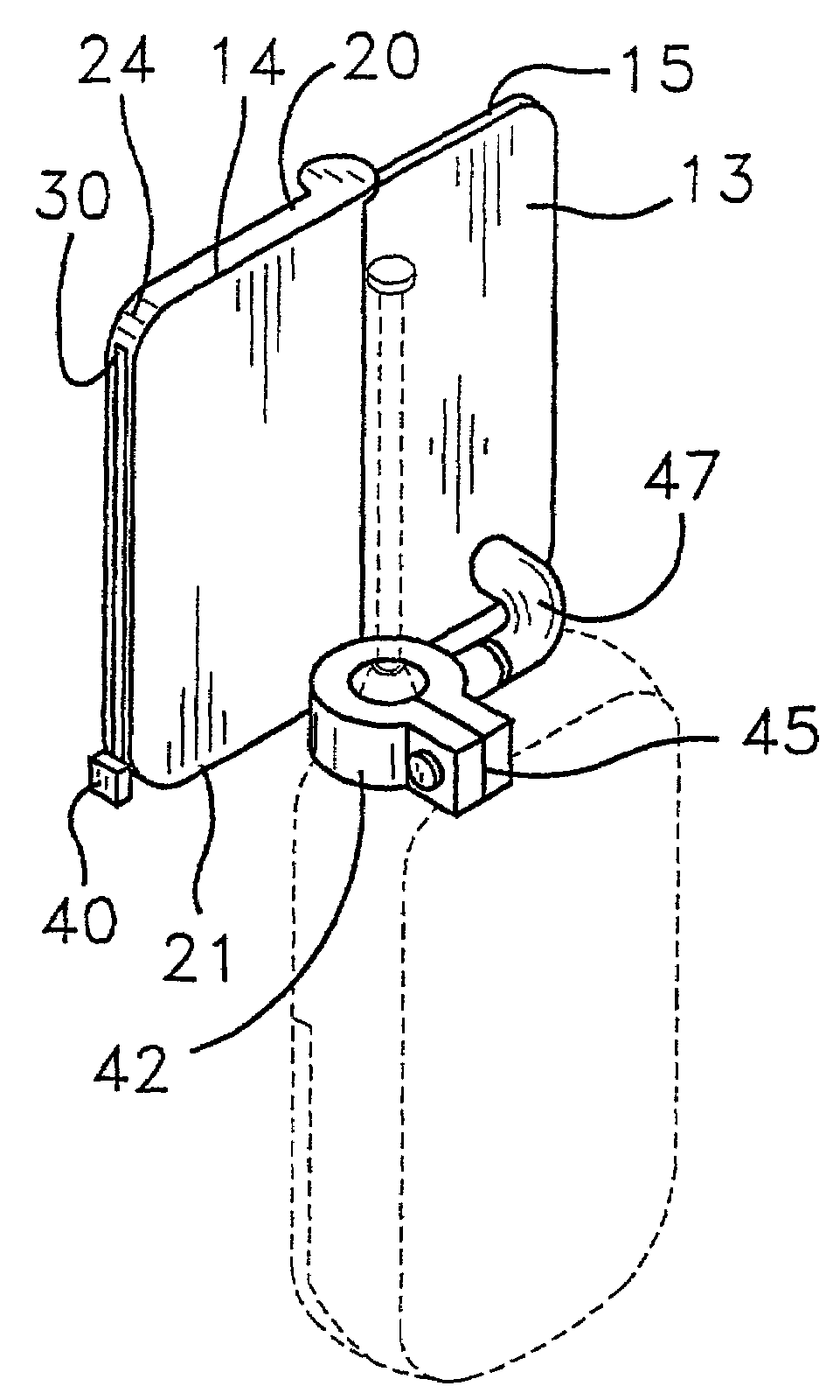
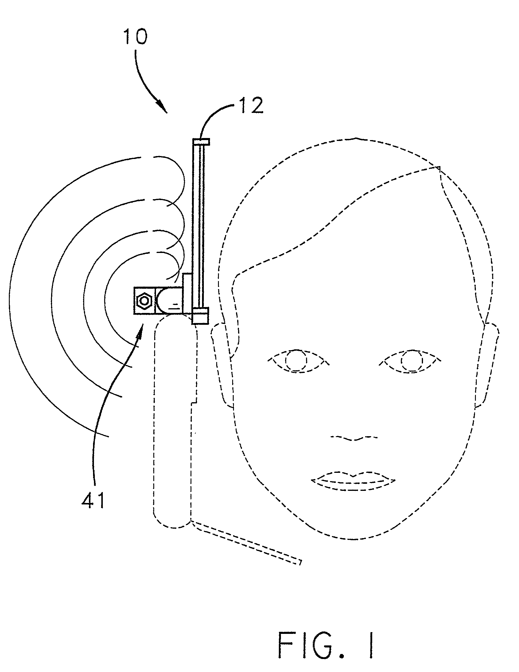
[0031]With reference now to the drawings, and in particular to FIGS. 1 through 5 thereof, a new electromagnetic shielding system embodying the principles and concepts of the present invention and generally designated by the reference numeral 10 will be described.

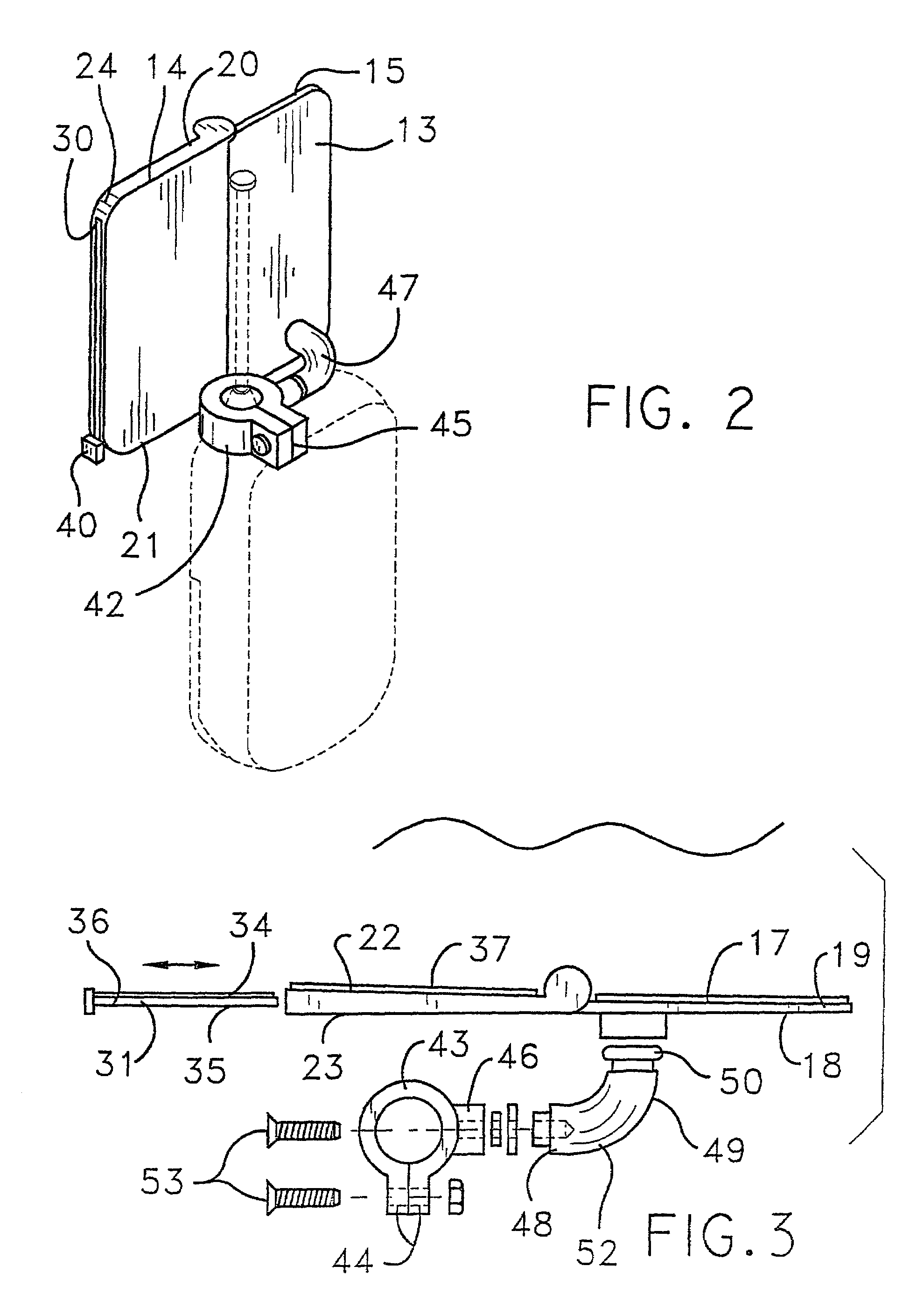
[0032]As best illustrated in FIGS. 1 through 5, the electromagnetic shielding system 10 generally comprises an expandable shield assembly 12 that includes a base panel 13 and an arm panel 14 that are pivotally coupled together for providing an expanded area of coverage for a user's head. The base panel 13 is removably mountable to an antenna of a cellular phone.

[0033]The base panel 13 has a first end 15, a second end 16, opposed front 17 and rear 18 planar surfaces and a peripheral edge surface 19. The base panel 13 may comprise a substantially lightweight rigid material such as, for example, a plastic.

[0034]The arm panel 14 has a first end 20, a second end 21, opposed front 22 and rear 23 planar surfaces and a peripheral ed...


PUM


Abstract

An electromagnetic shielding system for shielding a user's head from electromagnetic waves produced from an antenna of a cellular phone. The electromagnetic shielding system includes an expandable shield assembly that includes a base panel and an arm panel pivotally coupled together for providing an expanded area of coverage for a user's head. The base panel is removably mountable to the antenna of a cellular phone. An electromagnetic reflective member is mounted to the shield assembly for shielding a user from the electromagnetic waves. A coupling assembly is removably mountable to and extends between the shield assembly and the antenna of the cellular phone for positioning the expandable shield assembly between a stored position and a shielding position.

Description

BACKGROUND OF THE INVENTION[0001]1. Field of the Invention[0002]The present invention relates to electromagnetic shielding systems and more particularly pertains to a new electromagnetic shielding system for shielding a user's head from electromagnetic waves produced from a cellular phone. The cellular phone has at least a front face having a plurality of buttons and a display.[0003]2. Description of the Prior Art[0004]The use of electromagnetic shielding systems is known in the prior art. More specifically, electromagnetic shielding systems heretofore devised and utilized are known to consist basically of familiar, expected and obvious structural configurations, notwithstanding the myriad of designs encompassed by the crowded prior art which have been developed for the fulfillment of countless objectives and requirements.[0005]Known prior art includes U.S. Pat. No. 6,095,820; U.S. Pat. No. 5,666,125; U.S. Pat. No. 6,075,977; U.S. Pat. No. 5,657,386; U.S. Pat. No. 5,335,366; and U.S...

Claims


Application Information

Patent Timeline
Patent Type & Authority Patents(United States)
IPC IPC(8): H01Q1/52
CPCH01Q19/10H01Q1/245
Inventor BROWN, LARRY K.
Owner BROWN LARRY K
Why Eureka
Try Eureka