Rotation and/or tilt angle detection means for a ball and socket joint

a detection means and a technology for detecting the rotation and/or tilt angle, which are applied in the direction of instruments, speed/acceleration/shock measurement, couplings, etc., can solve the problems of disadvantageous disadvantageous coupling of a plurality of sensors, and insufficient measurement of the rotation and tilt angle, etc., to achieve simple sensor array and simple design

Inactive Publication Date: 2007-01-30
ZF LEMFOERDER METALLWAREN AG
View PDF10 Cites 58 Cited by
  • Summary
  • Abstract
  • Description
  • Claims
  • Application Information

AI Technical Summary

Benefits of technology

[0006]The object of the present invention is therefore to provide a sensor of a relatively simple design or a simple sensor array by means of which the rotary and tilting movement of a ball and socket joint can be determined.
[0009]The means according to the present invention makes it possible to detect both the rotary and tilting movement of the ball and socket joint, and the sensor advantageously operates in a contactless manner. The present inventions makes provisions for at least one magnet to be arranged at or in the joint ball or the ball pivot. The resulting magnetic field generated is made visible by means of a magnetooptic effect. An optical detection means then determines the visualized magnetic field, and the rotation or tilting of the ball and socket joint can be determined by the magnetic field, which is altered in relation to the initial position.
[0010]Two permanent magnets are advantageously arranged in the pole area of the joint ball in parallel to and at a certain distance from one another. The magnets may be manufactured, in principle, from any desired material and have any desired shape, especially a rod shape. NdFeB magnets, which have a diameter of 1 mm and a length of 2 mm, are advantageously used, one magnet with its north pole being directed toward the surface of the joint ball and the other magnet being directed with its south pole toward the surface of the joint ball. It is possible for the pole area of the joint ball to be flattened. A space is formed as a result between the outer surface of the ball and the ball socket, which space can be used as a grease space or grease depot. If this space is filled with lubricating grease, it is guaranteed that the ball and socket joint will continuously lubricate itself. It is possible in case of such an embodiment of the ball and socket joint for the display device to be arranged in the form of a magnetooptic plate directly behind the grease space or to form a wall area of the grease space itself. The magnetic field generated by the magnets is advantageously not affected adversely or deflected in the latter case by the material of the bearing shell. As a result, the resulting magnetic field of the at least one magnet can be displayed or detected relatively accurately. The display device may also be provided at the ball and socket joint housing or made in one piece therewith.

Problems solved by technology

However, the measurement of the rotation and tilt angles has been an essential problem for the use of ball and socket joints so far.
The drawback of these sensors is that they determine exclusively the rotary movement and do not detect the tilting movement of the ball and socket joint.
If the tilting movement is to be detected as well, a complicated coupling of a plurality of sensors is disadvantageously necessary.
Sensors operating on the basis of Hall sensors disadvantageously have a high sensitivity to external magnetic fields and temperature changes.
It is also disadvantageous in case of the use of Hall sensors that the aging of the exciting magnets is not compensated.
Furthermore, the calculation of the rotation and tilt angles is very complicated, and it is necessary to record a characteristic diagram in most cases.

Method used


Image

  • Rotation and/or tilt angle detection means for a ball and socket joint
  • Rotation and/or tilt angle detection means for a ball and socket joint
  • Rotation and/or tilt angle detection means for a ball and socket joint

Examples


Embodiment Construction

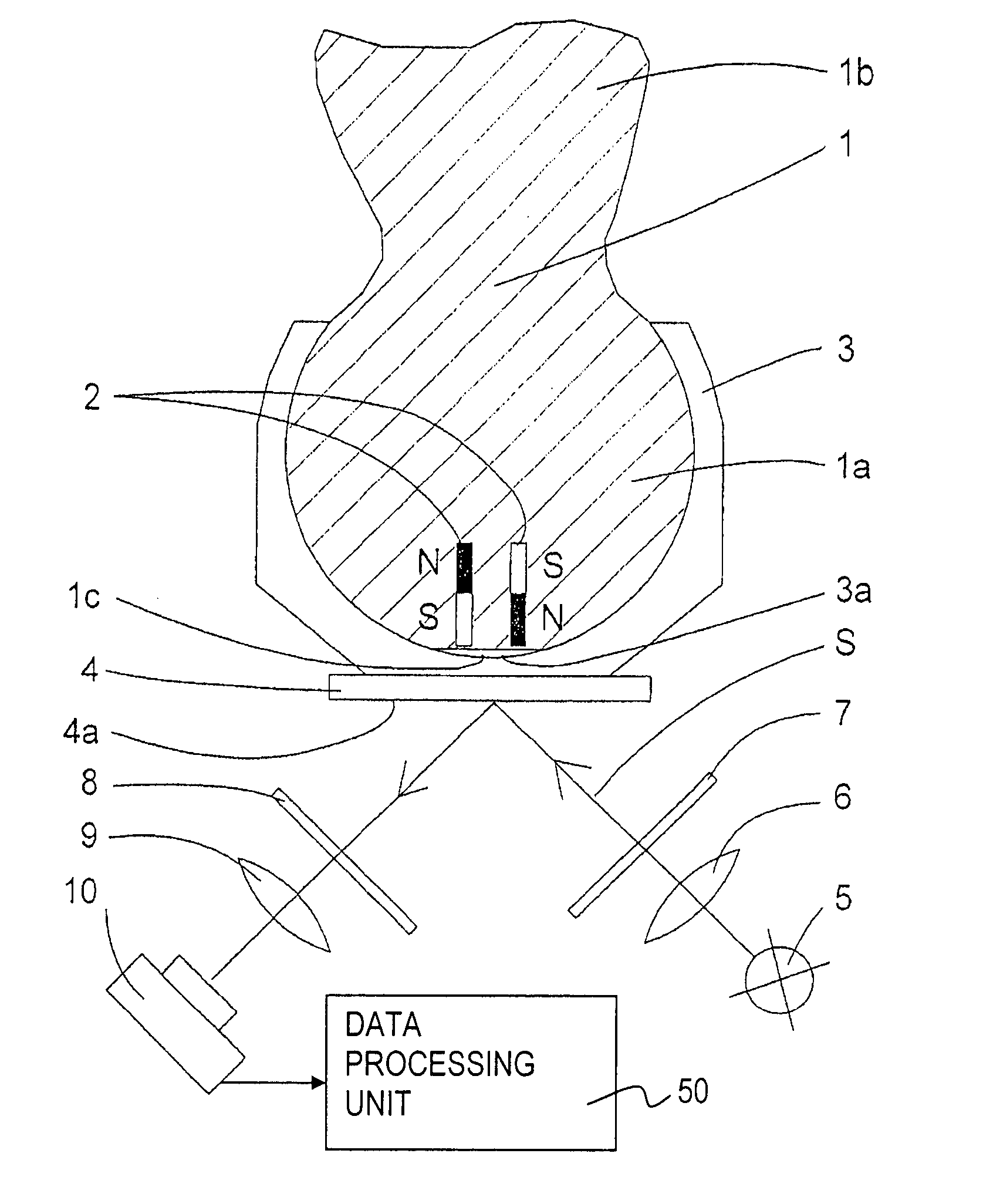
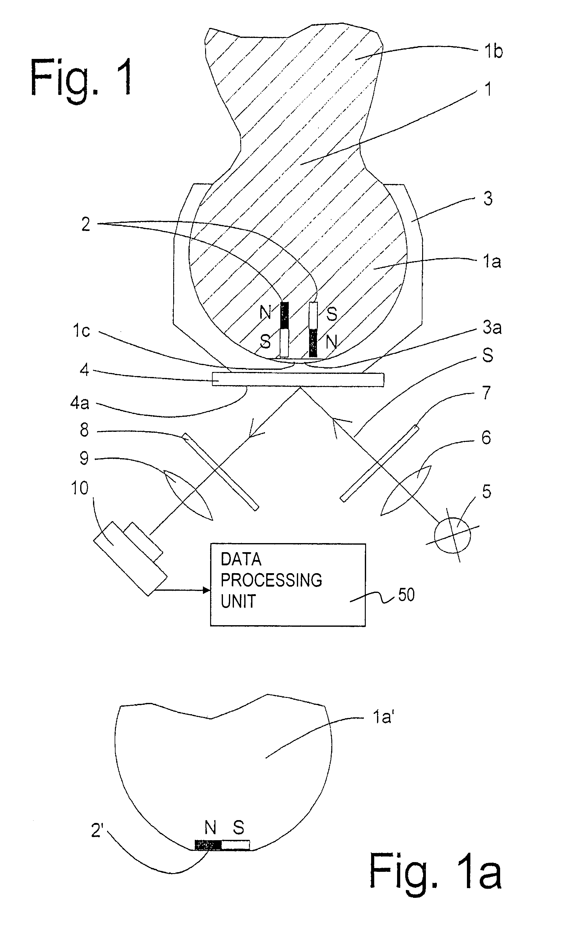
[0020]FIG. 1 shows a cross-sectional view through a ball and socket joint with a rotation and / or tilt angle detection means according to the present invention. The ball and socket joint comprises a ball pivot 1, which is inserted into a bearing shell (ball socket 3) with its joint ball 1a made in one piece with the pivot 1b. The pole face 1c of the joint ball 1a is flattened, so that a free space 3a, which can be used as a grease space or grease depot, is formed between the joint ball 1a and the bearing shell 3. Two permanent magnets 2 are arranged at spaced locations and in parallel to one another in the joint ball 1a in the pole area, one permanent magnet 2 being directed or pointing with its north pole N and the other permanent magnet 2 with its south pole S in the direction of the pole face 1c. The permanent magnets 2 may either be inserted into openings and firmly connected with the joint ball 1a, e.g., by means of an adhesive. However, it is also possible to integrate or to ca...


PUM


Abstract

A rotation and / or tilt angle detection device for a ball and socket joint is provided wherein at least one magnet (2), especially a permanent magnet, is arranged in the joint ball (1a), wherein a display device (4) displays the magnetic field of the at least one magnet (2) by means of the magnetooptic effect. An image detection deice (10) detects the information displayed by the display device (4). A data processing unit (50) calculates the relative position of the joint ball (1a) and the ball socket (3) of the ball and socket joint on the basis of the information detected.

Description

CROSS REFERENCE TO RELATED APPLICATION[0001]This is a continuation of and claims the benefit (35 U.S.C. § 120 and 365(c)) of copending International Application PCT / DE 2003 / 003102 of Sep. 17, 2003, which designated inter alia the United States and which claims the priority of German Application DE 102 43 399.2 of Sep. 18, 2002. The entire contents of each application is hereby incorporated by reference in its entirety.FIELD OF THE INVENTION[0002]The present invention pertains to a rotation angle and tilt angle detection means for a ball and socket joint.BACKGROUND OF THE INVENTION[0003]Ball and socket joints are important mechanical components, because they allow three degrees of freedom. Only joysticks and vehicle components shall be mentioned here as examples of two typical applications of ball and socket joints. However, the measurement of the rotation and tilt angles has been an essential problem for the use of ball and socket joints so far. A great variety of rotation angle sen...

Claims


Application Information

Patent Timeline
Patent Type & Authority Patents(United States)
IPC IPC(8): F16D1/12G01B7/30B60G7/02B60G17/00B60G17/019F16C11/06G01B7/00G01B11/26G01D5/34
CPCB60G17/019G01D5/344B60G2204/11B60G2401/14B60G2401/17B60G2204/416G01D5/34G01R33/032
Inventor KRUSE, JOCHENSPRATTE, JOACHIMKLANK, MICHAELHAGEDORN, OLIVERDOTSCH, HORST
Owner ZF LEMFOERDER METALLWAREN AG
Why Eureka
Try Eureka