Deflector style exhaust manifold

a technology of exhaust manifold and deflector, which is applied in the direction of engines, mechanical equipment, machines/engines, etc., can solve the problems of reduced exhaust output depending on the exhaust order of the engine cylinder, difficult designs, and inability to adjust the exhaust order, so as to reduce undesirable pneumatic interaction and optimize the exhaust flow

Active Publication Date: 2007-02-06
FCA US
View PDF7 Cites 21 Cited by
  • Summary
  • Abstract
  • Description
  • Claims
  • Application Information

AI Technical Summary

Benefits of technology

[0005]Accordingly, one aspect of the present invention is to provide an exhaust manifold that is capable of reducing undesirable pneumatic interaction between cylinders and optimizing exhaust flow.
[0006]Another aspect of the present invention is to provide an exhaust manifold that requires a minimal amount of space within the engine compartment while reducing undesirable pneumatic interaction between cylinders.

Problems solved by technology

While these and other prior manifold constructions control flow of engine exhaust gas as disclosed, one drawback is that such constructions can result in exhaust interference (i.e. a portion of the engine exhaust gas reflected back up the exhaust tube toward non-firing upstream engine cylinders) and reduced output depending on the exhaust order of the engine cylinders.
However, the compact size of modern vehicle engine compartments makes such designs difficult due to their bulky configurations.

Method used


Image

  • Deflector style exhaust manifold
  • Deflector style exhaust manifold
  • Deflector style exhaust manifold

Examples


Embodiment Construction

[0014]The following description of the preferred embodiment(s) is merely exemplary in nature and is in no way intended to limit the invention, its application, or uses.

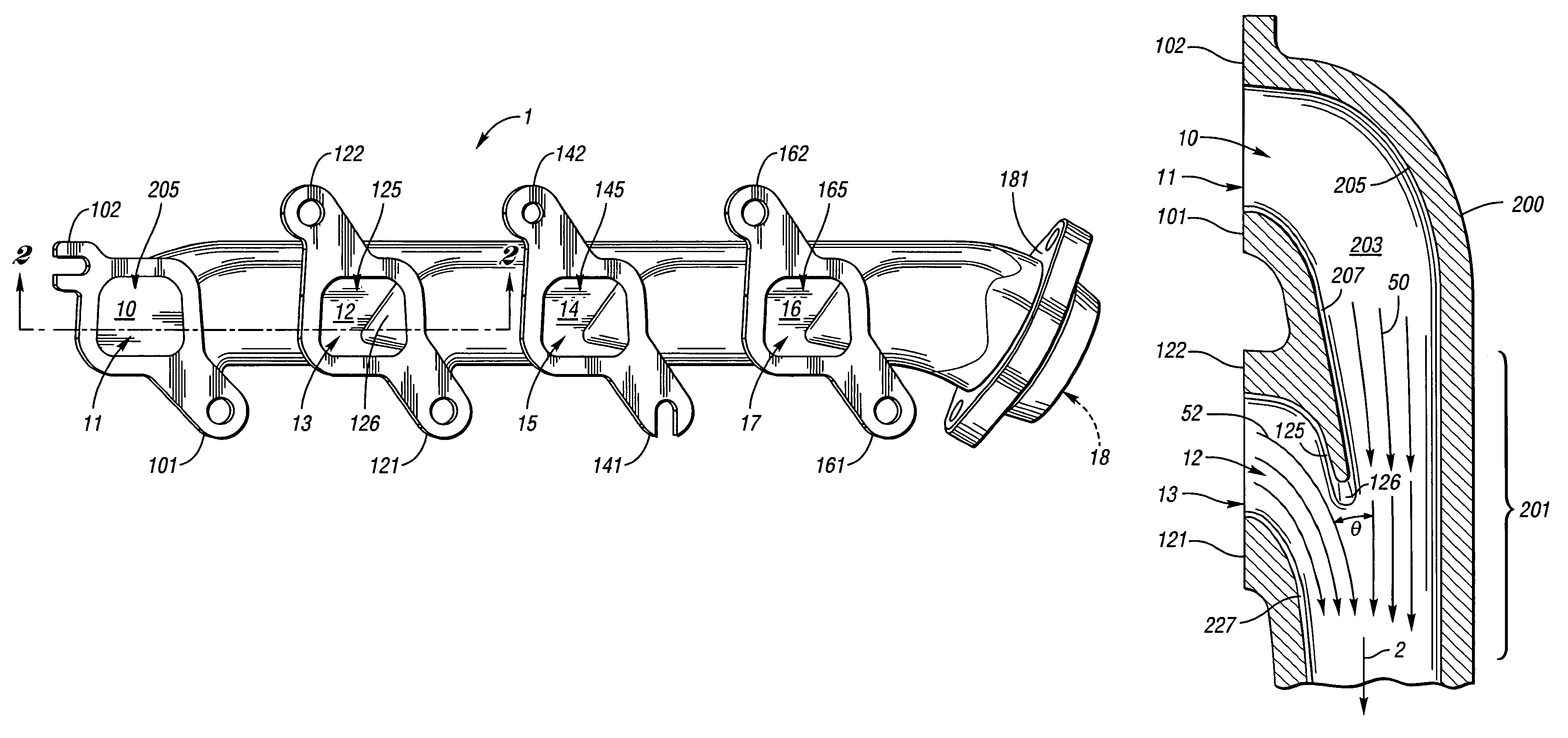
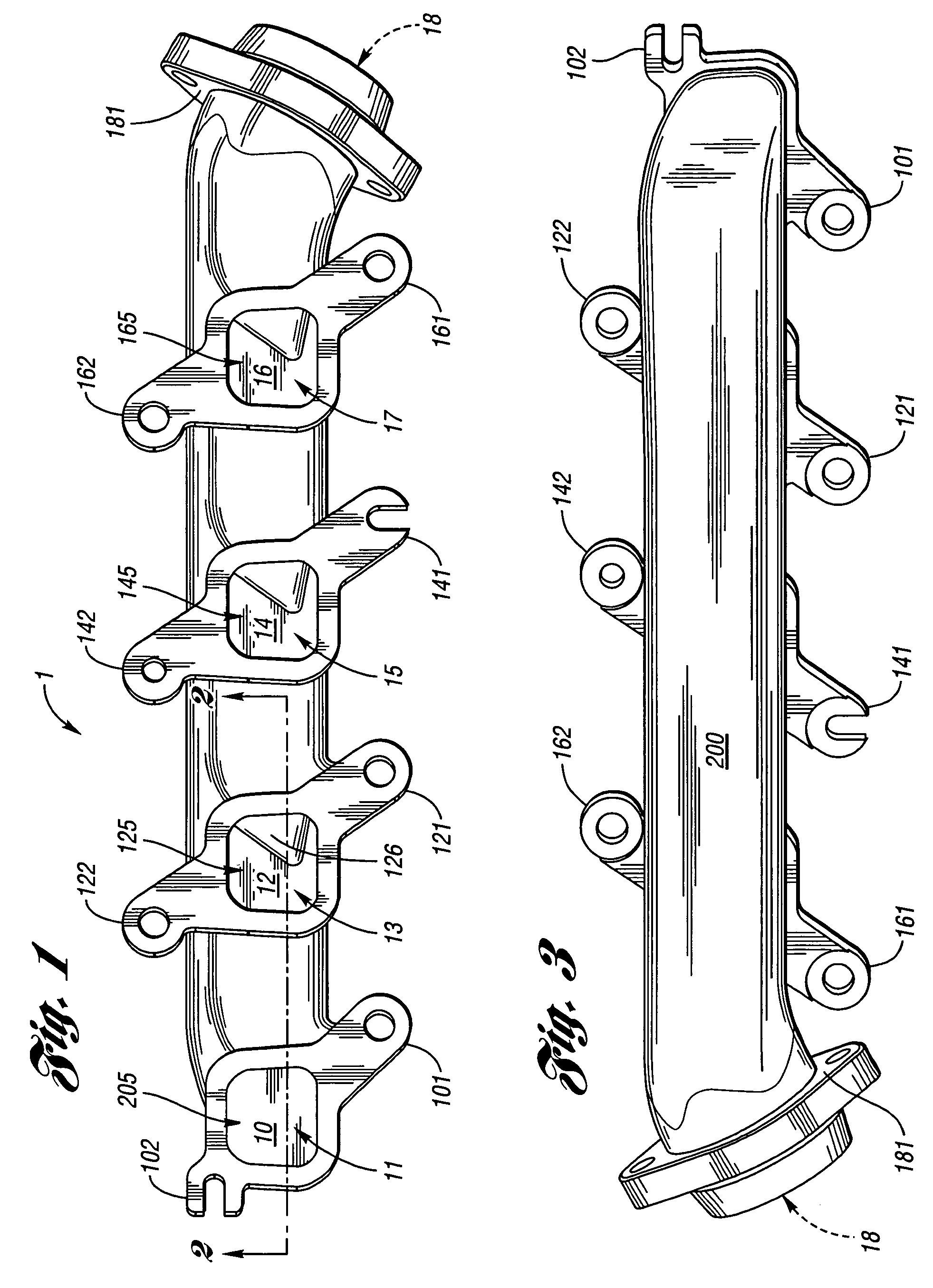
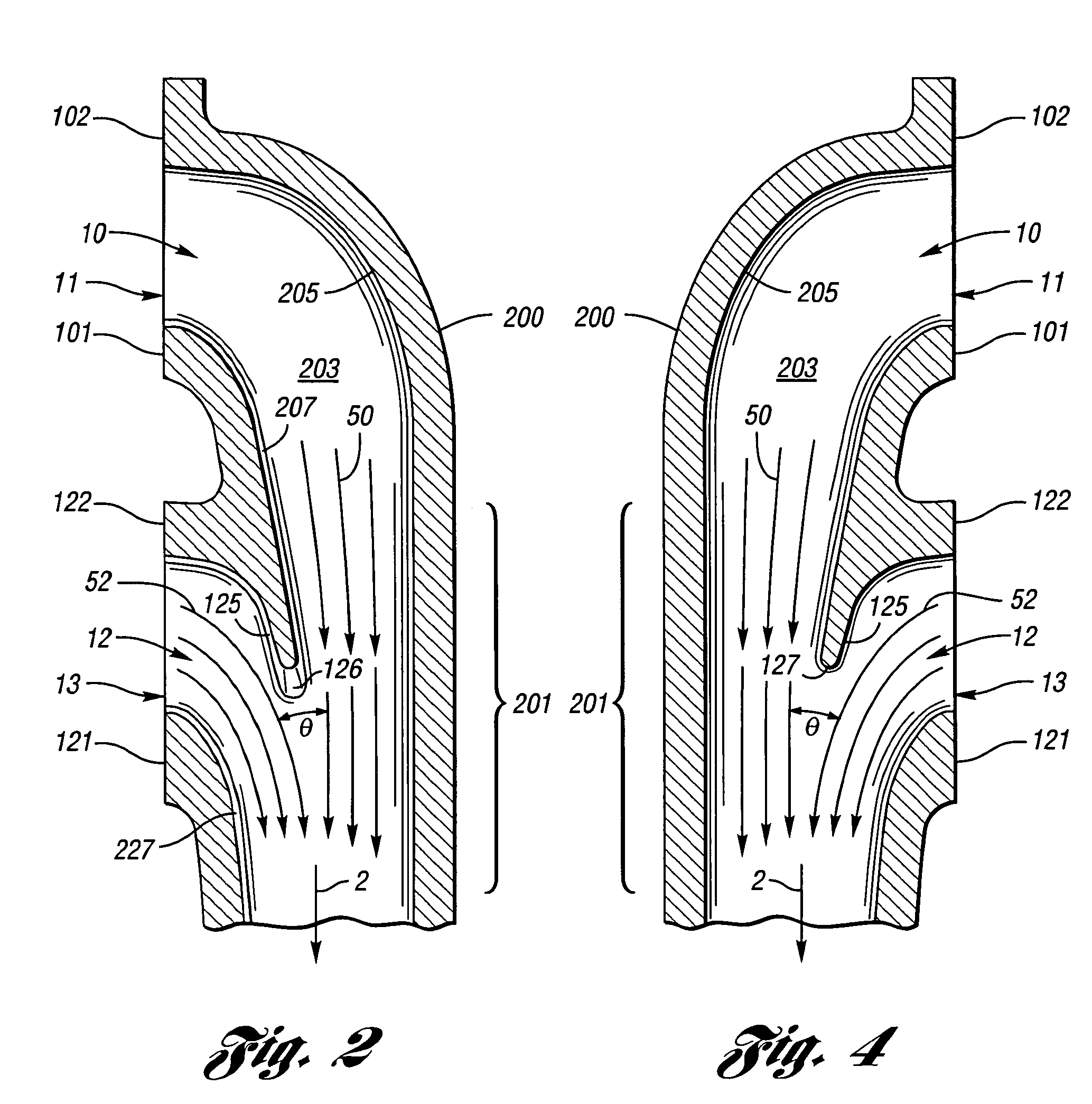
[0015]Turning now in greater detail to the drawings particularly FIG. 1, an exhaust manifold 1 according to an exemplary embodiment of the invention adapted for use with an internal combustion engine is shown. In the illustrated embodiment, an exhaust manifold 1 is adapted to be attached to a right cylinder assembly of a V-8 type internal combustion engine (not shown). The exhaust manifold 1 forms a plurality of exhaust gas inlet branch portions arranged in series. Referring to FIGS. 2 and 4, each exhaust gas inlet branch portion defines an inlet branch passage 10, 12, 14 and 16, respectively, having exhaust gas openings 11, 13, 15 and 17 open to flow of exhaust gas from the passages of the cylinder head as is well known in the art. The inlet branch passages 10, 12, 14 and 16 each receive a discharge of exhaust gas fr...


PUM


Abstract

An exhaust manifold is provided with deflector members positioned between downstream gas inlets and a main gas passage. The deflector members redirect the flow of exhaust gas from the inlets into the general direction of the gas flowing in the main passage as the exhaust gas enters the main passage.

Description

FIELD OF THE INVENTION[0001]The present invention relates to an exhaust manifold for controlling combustion gases and more particularly to arrangements for reducing pneumatic interaction between cylinders and optimizing exhaust flow in an exhaust manifold.BACKGROUND OF THE INVENTION[0002]Prior to the present invention, various exhaust manifolds and methods of controlling exhaust gases have been disclosed in the prior art. U.S. Pat. No. 2,230,666 which issued on Feb. 4, 1941 and is entitled “Exhaust Gas Collector” discloses a plurality of laterally spaced exhaust pipes fluidly connected to the cylinders of an associated internal combustion engine open to a diverging funnel-like main exhaust tube providing reduced back pressure and thereby increasing the power of the engine. U.S. Pat. No. 4,288,988 which issued on Sep. 15, 1981 and is entitled “Method and Apparatus for Improving the Gas Flow in an Internal Combustion Engine Exhaust Manifold” discloses a method and apparatus for dampin...

Claims


Application Information

Patent Timeline
Patent Type & Authority Patents(United States)
IPC IPC(8): F01N7/10F01N13/10
CPCF01N13/10F01N2260/16F01N2260/06
Inventor RUEHLE, EDWARD A.
Owner FCA US
Why Eureka
Try Eureka