Deflector style exhaust manifold

a technology of exhaust manifold and deflector, which is applied in the direction of exhaust treatment, machines/engines, mechanical equipment, etc., can solve the problems of reducing the output depending on the exhaust order of the engine cylinder, the main exhaust gas passage is not sufficient to prevent undesirable pneumatic interaction between the cylinder, and the exhaust interference of the exhaust pipe. to achieve the effect of optimizing the exhaust flow and reducing undesirable pneumatic interaction

Inactive Publication Date: 2010-11-16
FCA US
View PDF9 Cites 12 Cited by
  • Summary
  • Abstract
  • Description
  • Claims
  • Application Information

AI Technical Summary

Benefits of technology

[0006]Accordingly, one aspect of the present invention is to provide an exhaust manifold that is capable of reducing undesirable pneumatic interaction between cylinders and optimizing exhaust flow.
[0007]Another aspect of the present invention is to provide an exhaust manifold that permits the main exhaust gas passage and the engine's exhaust ports to be in non-coplanar fluid communication with each other while reducing undesirable pneumatic interaction between cylinders.

Problems solved by technology

While these and other prior manifold constructions control flow of engine exhaust gas as disclosed, one drawback is that such constructions can result in exhaust interference (i.e. a portion of the engine exhaust gas reflected back up the exhaust tube toward non-firing upstream engine cylinders) and reduced output depending on the exhaust order of the engine cylinders.
However, the space restrictions within the engine compartment of the modern motor vehicle may require that the main exhaust gas passage and the engine's exhaust ports are not co-planar with each other.
In such an arrangement, the mere provision of a deflector member between each inlet branch passage and the main exhaust gas passage is not sufficient to prevent undesirable pneumatic interaction between cylinders.

Method used


Image

  • Deflector style exhaust manifold
  • Deflector style exhaust manifold
  • Deflector style exhaust manifold

Examples


Embodiment Construction

[0016]The following description of the preferred embodiment(s) is merely exemplary in nature and is in no way intended to limit the invention, its application, or uses.

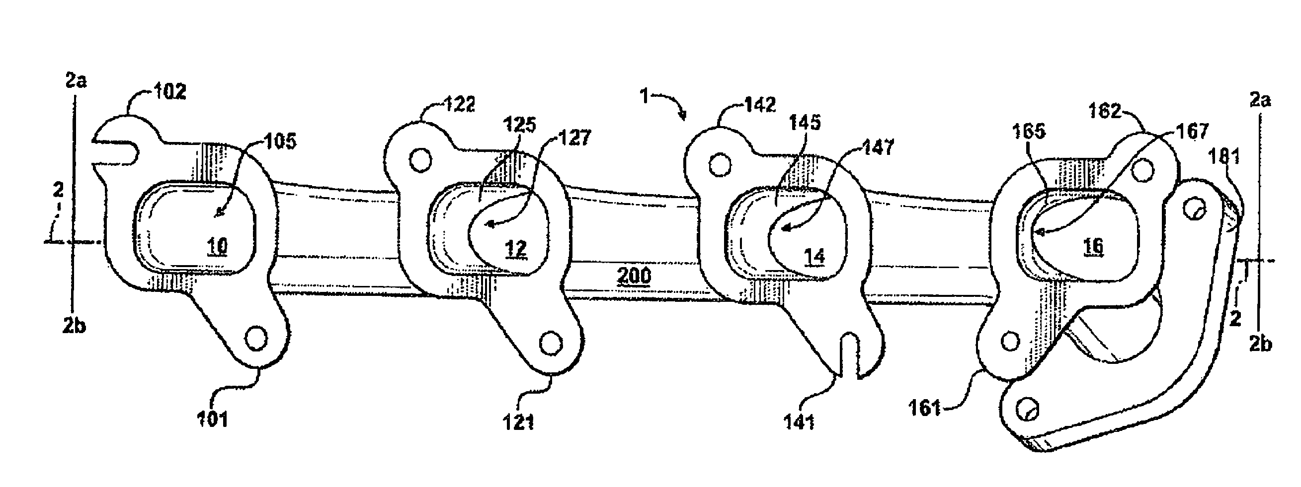
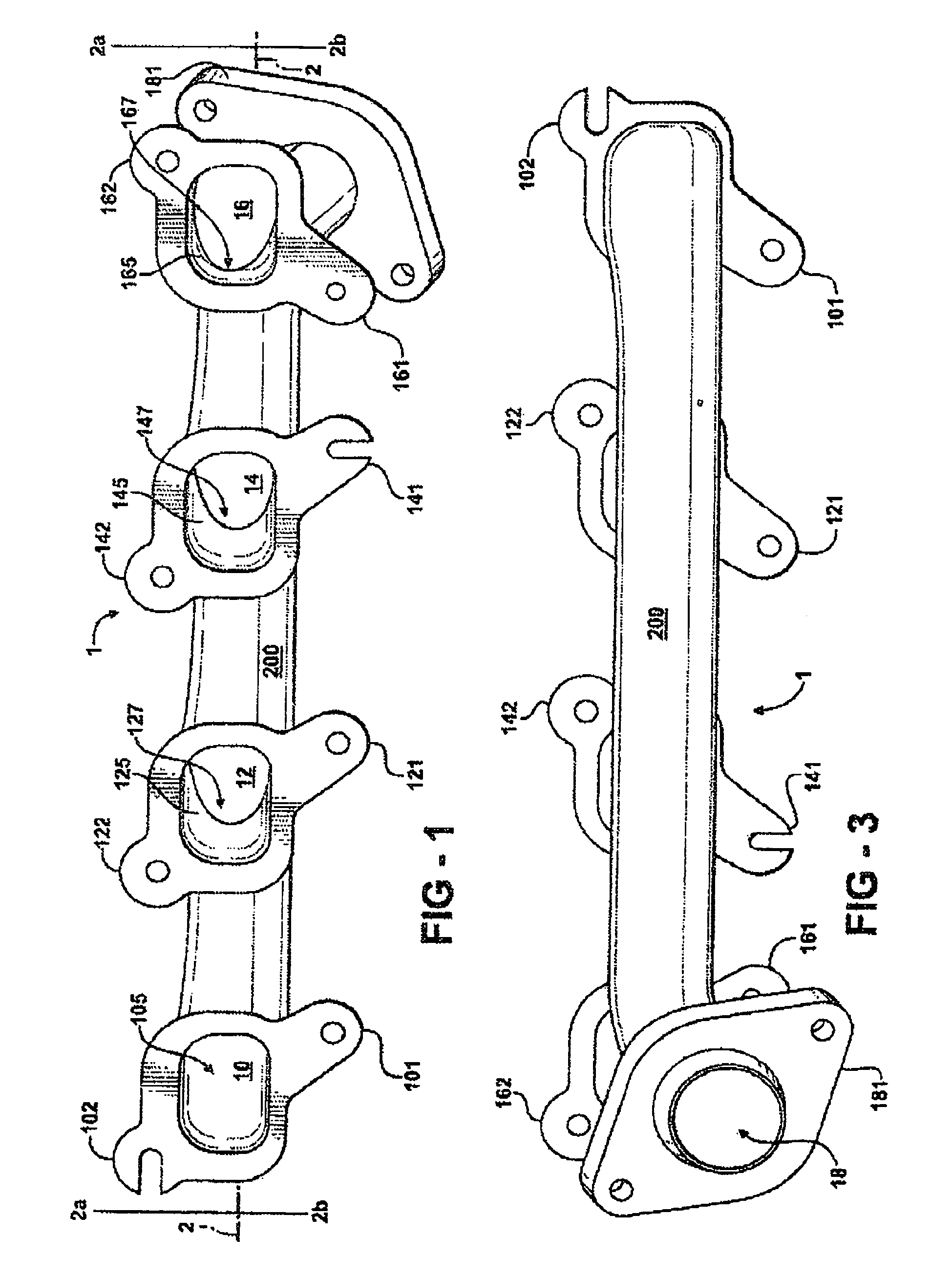
[0017]Turning now in greater detail to the drawings particularly FIGS. 1 and 3, an exhaust manifold 1 according to an exemplary embodiment of the invention adapted for use with an internal combustion engine is shown. In the illustrated embodiment, an exhaust manifold 1 is adapted to be attached to a right cylinder assembly of a V-8 type internal combustion engine (not shown). The exhaust manifold 1 consists of a plurality of coplanar exhaust gas inlet branch portions arranged in series and a main exhaust gas passage contained within a main housing 200 on a second lower plane which is arranged to be in fluid non-coplanar communication with the exhaust gas inlet branch portions of the manifold 1.

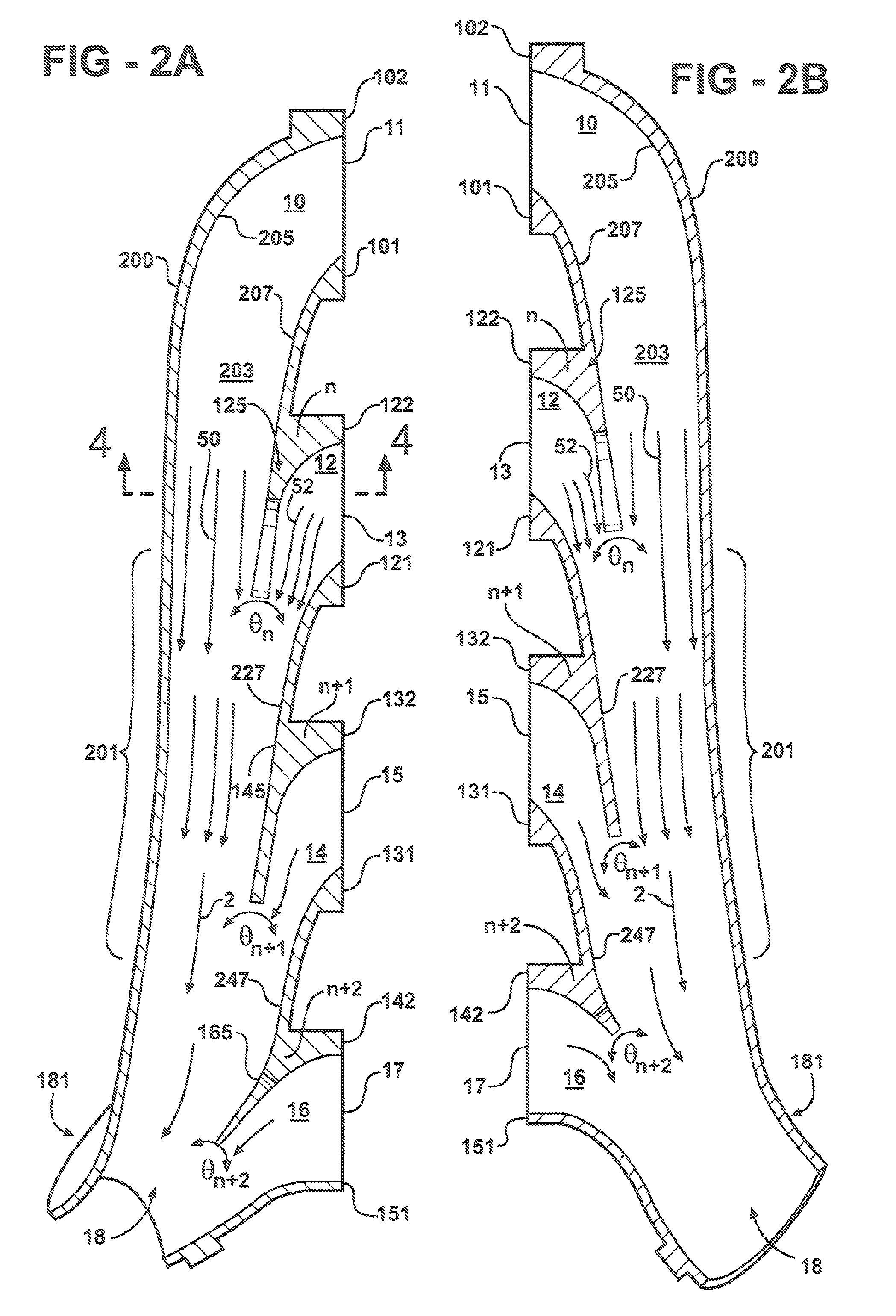
[0018]Referring to FIGS. 2A and 2B, each exhaust gas inlet branch portion defines an inlet branch passage 10, 12, 14 and 16, r...


PUM


Abstract

An exhaust manifold for an engine having at least one combustion chamber and multiple exhaust valves arranged on a first plane is provided with a housing formed to provide a longitudinally extending main exhaust gas passage on a second plane terminating in an outlet at one end. A plurality of discrete, laterally spaced, inlet branch passages include a floor and a ceiling which are initially level with the exhaust valve for a distance equal to one-half the width of the inlet branch passage prior to sloping downward toward the main exhaust gas passage. One of the inlet branch passages is positioned at an end of the housing opposite the exhaust gas passage outlet. The remaining inlet branch passages include integrally formed deflector members arranged to provide an angular change of flow direction requiring exhaust gas to enter the main exhaust gas passage in the downstream direction.

Description

FIELD OF THE INVENTION[0001]The present invention relates to an improved exhaust manifold for controlling combustion gases and more particularly to arrangements for reducing pneumatic interaction between cylinders and optimizing exhaust flow in an exhaust manifold.BACKGROUND OF THE INVENTION[0002]Prior to the present invention, various exhaust manifolds and methods of controlling exhaust gases have been disclosed In the prior art. U.S. Pat. No. 2,230,666 which issued on Feb. 4, 1941 and is entitled “Exhaust Gas Collector” discloses a plurality of laterally spaced exhaust pipes fluidly connected to the cylinders of an associated internal combustion engine open to a diverging funnel-like main exhaust tube providing reduced back pressure and thereby increasing the power of the engine. U.S. Pat. No. 4,288,988 which issued on Sep. 15, 1981 and is entitled “Method and Apparatus for Improving the Gas Flow in an Internal Combustion Engine Exhaust Manifold” discloses a method and apparatus f...

Claims


Application Information

Patent Timeline
Patent Type & Authority Patents(United States)
IPC IPC(8): F01N1/00F01N13/10
CPCF01N13/10F01N2240/20
Inventor RUEHLE, EDWARD A.
Owner FCA US
Why Eureka
Try Eureka