Retractor instrumentation for total hip arthroplasty, and methods of using same

a technology of trajectories and total hip arthroplasty, which is applied in the field of orthopaedics, can solve the problems of reducing the number of assistants involved, increasing the difficulty of surgeons performing surgery, and mechanical complexity of the type of equipmen

Inactive Publication Date: 2007-02-06
ZIMMER TECH INC
View PDF17 Cites 12 Cited by
  • Summary
  • Abstract
  • Description
  • Claims
  • Application Information

AI Technical Summary

Problems solved by technology

More specifically, minimally invasive surgical techniques involve less cutting through muscles, less blood loss and often shorter hospital stays.
Although such minimally invasive hip replacement surgical techniques are more beneficial to the patient, they tend to be more difficult for a surgeon to perform due to the limited access to the surgical site by virtue of the smaller incision in the patient.
The latter type of equipment is relatively complicated mechanically, but it may reduce the number of assistants involved as compared to the handheld retractors.
In some cases, prior art retractor methods were beneficial for part of the hip replacement surgery but not for all aspects of the surgery.
However, when the surgeon then attempted to install the stem in the patient's femur, it was often the case that the upstanding Charnley pins would interfere with part of that procedure.
Thus, in some cases, one or more of the Charnley pins were removed, thereby reducing the retraction function of the pins.
Moreover, given the tendency towards the minimally invasive hip replacement surgery, with its associated reduced incision length, prior art methodologies of retraction may not be readily adapted or employed in such minimally invasive procedures.
Another problem associated with total hip replacement surgery involves insuring that after the operation is completed the patient's leg is the appropriate length.
Historically, problems have arisen with hip replacement surgery wherein the leg length of the patient after surgery is less than ideal, i.e., it is too short or too long relative to its pre-operative length.
This may be due to, among other things, the improper positioning of the hip replacement components within the patient.
Problems also arose in situations where it was desired to shorten or lengthen a patient's natural leg length during hip replacement surgery.
That is, due to a variety of reasons, the surgeon was unable to obtain a desired or target length for the patient's leg after the hip replacement surgery is complete.
Fundamentally, problems with achieving correct leg length involved difficulty in identifying and maintaining various reference points that would thereby allow the surgeon to confirm the correct positioning of the patient's leg with the hip replacement components installed in the patient.

Method used


Image

  • Retractor instrumentation for total hip arthroplasty, and methods of using same
  • Retractor instrumentation for total hip arthroplasty, and methods of using same
  • Retractor instrumentation for total hip arthroplasty, and methods of using same

Examples


Embodiment Construction

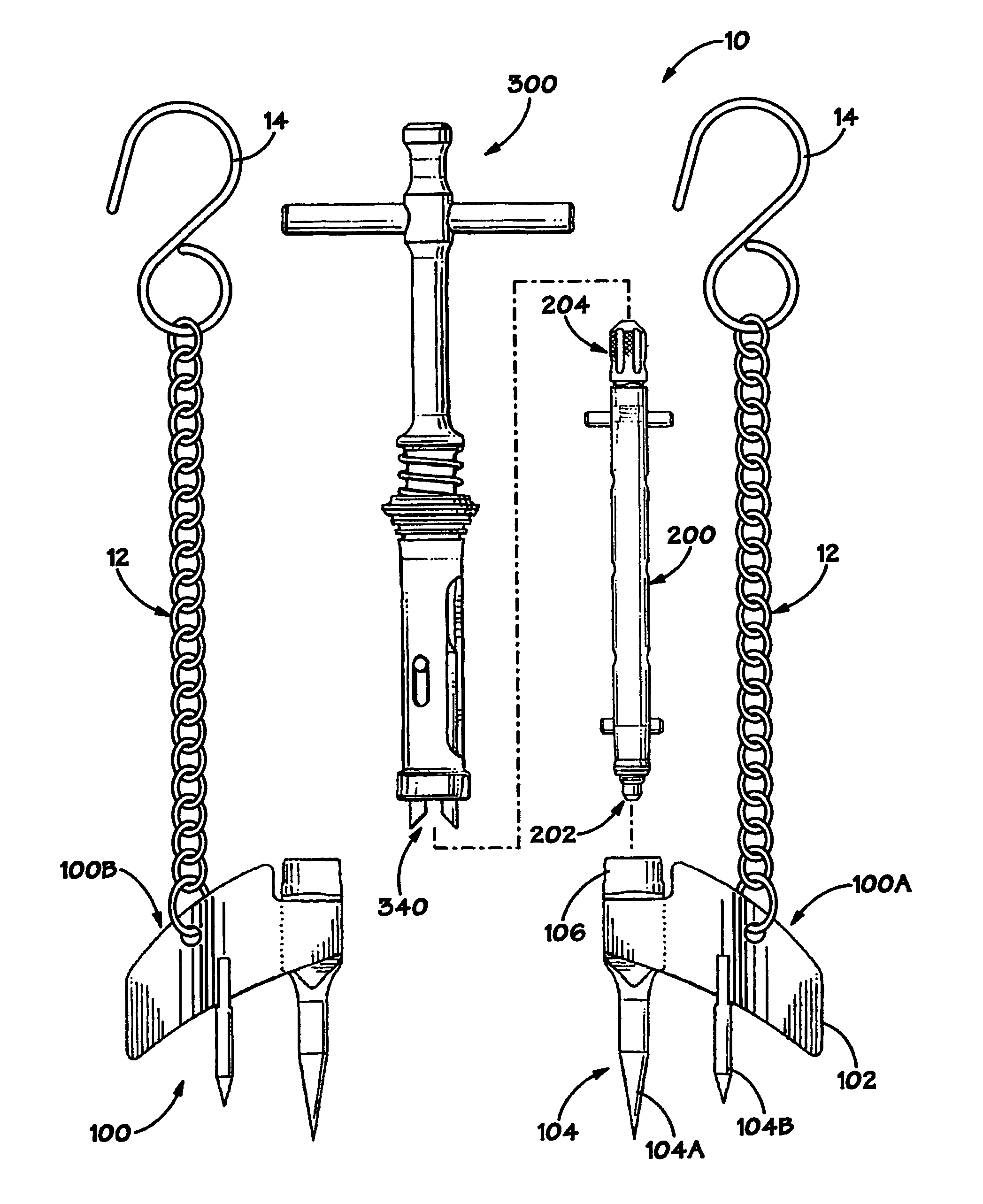
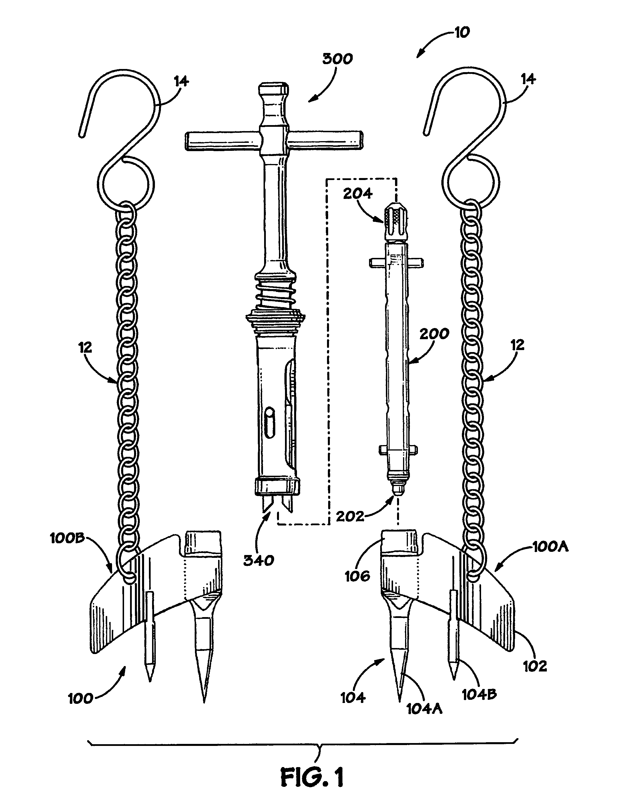
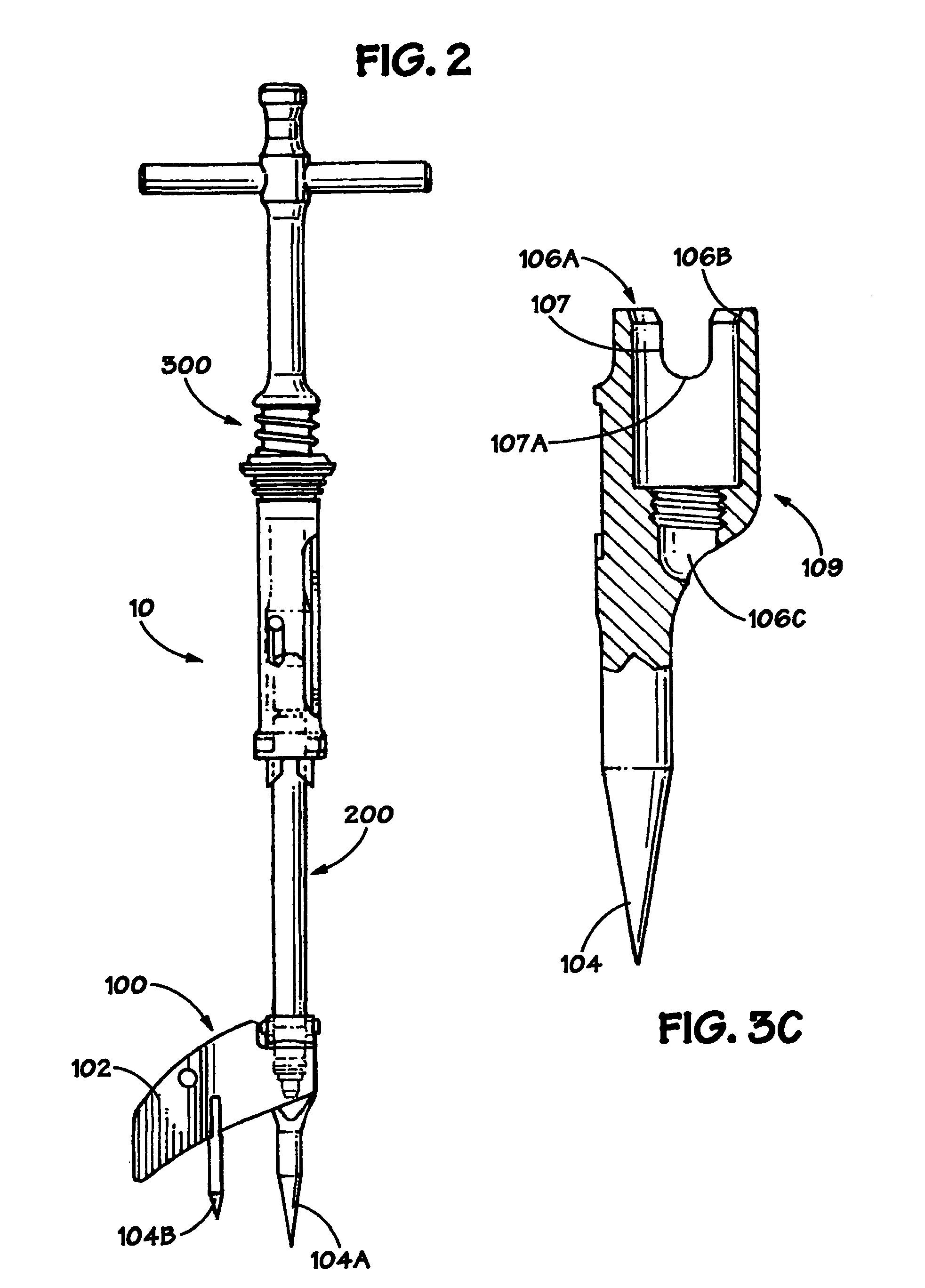
[0026]Illustrative embodiments of the invention are described below. In the interest of clarity, not all features of an actual implementation are described in this specification. It will of course be appreciated that in the development of any such actual embodiment, numerous implementation-specific decisions must be made to achieve the developers' specific goals, such as compliance with system-related and business-related constraints, which will vary from one implementation to another. Moreover, it will be appreciated that such a development effort might be complex and time-consuming, but would nevertheless be a routine undertaking for those of ordinary skill in the art having the benefit of this disclosure.

[0027]The present invention will now be described with reference to the attached figures. The words and phrases used herein should be understood and interpreted to have a meaning consistent with the understanding of those words and phrases by those skilled in the relevant art. No...


PUM


Abstract

The present invention is directed to retractor instrumentation for total hip arthroplasty, and methods of using same. In one illustrative embodiment, the device comprises a body, a first pin coupled to the body, and a second pin coupled to said body, wherein at least a portion of said first and second pins are adapted to penetrate human bone. In a further illustrative embodiment, a retractor instrumentation set comprises a retractor device, a shaft that is adapted to be removably coupled to the retractor device, and an inserter that is adapted to be removably coupled to the shaft.

Description

BACKGROUND OF THE INVENTION[0001]1. Field of the Invention[0002]The present invention is generally related to the field of orthopedics, and, more particularly, to retractor instrumentation for total hip arthroplasty, and methods of using same.[0003]2. Description of the Related Art[0004]In the field of orthopedics, hip replacement is very common. Each year an estimated 300,000 people undergo hip replacement surgery. That number is expected to increase as the population continues to age, particularly within the United States. Most people have hip replacement surgery because of osteoarthritis, a degenerative joint disease. Basically, hip replacement surgery typically involves positioning a cup, having a plastic liner, in the pelvis, and positioning a stem down inside the femur. A ball on top of the stem is positioned within the cup in a ball-and-socket arrangement thereby allowing the hip to move normally.[0005]Standard hip replacement surgery usually involves a relatively large 10–12...

Claims


Application Information

Patent Timeline
Patent Type & Authority Patents(United States)
IPC IPC(8): A61B1/32A61B17/02A61F5/00
CPCA61B17/025A61B2017/0275
Inventor GUSTKE, KENNETH A.JONES, III, RICHARD E.DYE, JR., DONALD W.
Owner ZIMMER TECH INC
Why Eureka
Try Eureka