Virtual trial reduction system for hip arthroplasty and coordinate systems therefor

a hip arthroplasty and virtual trial technology, applied in the field of apparatus and methods for facilitating total hip arthroplasty, can solve the problem of inefficiency of all these methods

Active Publication Date: 2011-12-13
MURPHY STEPHEN B
View PDF15 Cites 28 Cited by
  • Summary
  • Abstract
  • Description
  • Claims
  • Application Information

AI Technical Summary

Benefits of technology

[0007]In accordance with the present invention, I provide an apparatus and method for accurately and efficiently identifying the positions of the pelvis and the femur during surgery; accurately and efficiently placing a trial or real acetabular prosthesis into the pelvis, as well as a trial or real femoral prosthesis into the femur; and then performing a virtual trial reduction of the hip such as in total hip arthroplasty.
[0008]The invention makes use of surgical navigation elements that have come into recent use in surgical procedures. Surgical navigation systems use light, sound (specifically, ultrasound) or electromagnetic signals to determine the position of reference elements in an operating room. For example, a reference element placed on a digitizing probe can be tracked by a sensing system in the operating room so as to determine its position very accurately. Knowing the location in three-dimensional space (i.e., the operating room) of the reference elements, and knowing the location of this element with respect to the tip of the probe on which it is mounted, the location of the tip of the probe (and thus anything with which it is in contact) can accurately be determined. Similarly, a reference element may be placed on a body segment such as the pelvis or femur. Critical points on the body segment can then be determined simply by tracking the relative position of the digitizing probe and the body segment. Additionally, line segments can easily be determined by digitizing pairs of points.
[0009]The present invention extends prior surgical navigation systems to enable the performance of a “virtual”, as opposed to a physical, trial reduction of the hip prior to its actual reduction on completion of the surgical procedure. In particular, in accordance with the present invention, initial measurements of significant parameters of the patient are made and stored. These measurements may include not only the distance between selected landmarks on the patient's pelvis and femur, which enables the surgeon to ensure that desired leg length is maintained or achieved by the operation, but also may include measurements of offset and of the free range of motion, among others, so that these parameters may also be verified after the operation, and the changes resulting from the surgery can be quantified.

Problems solved by technology

All of these methods are inefficient.

Method used


Image

  • Virtual trial reduction system for hip arthroplasty and coordinate systems therefor
  • Virtual trial reduction system for hip arthroplasty and coordinate systems therefor
  • Virtual trial reduction system for hip arthroplasty and coordinate systems therefor

Examples


Embodiment Construction

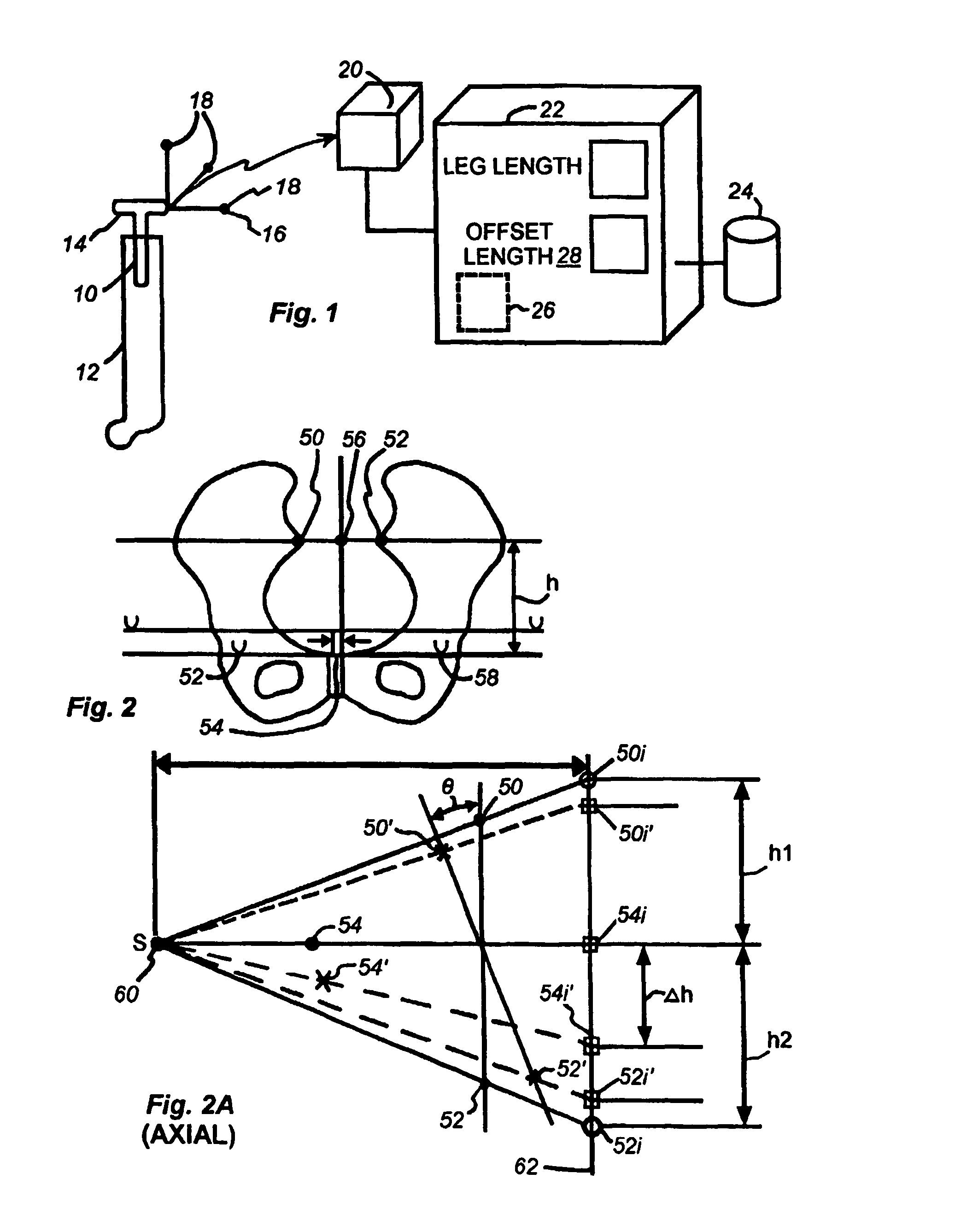
[0031]Referring now to FIG. 1, a broach 10 of known geometry that is being inserted within a femur 12 is connected to a broach handle 14 having a navigation frame 16 associated with it. The frame 16 carries a plurality of elements 18 extending in different directions in space. These elements may, for example, be infrared reflective elements such as are commonly used in conventional surgical navigation systems. A controller 20 receives signals from the elements 18 and from these determines the instantaneous position of the broach handle and thus of the broach. The controller may be of conventional type, e.g., an infrared emitter which receives reflections from the elements 18 and from these determines the position (i.e., location and orientation) of the frame with respect to itself and thus with respect to other objects of known relation to it.

[0032]The controller 20 in turn provides output to a monitor and controller 22 which provides the functions of an augmented surgical navigatio...


PUM


Abstract

A patient-specific pelvic coordinate system is produced from a single near AP intra-operative image of the patient, obviating the need for use of a patient tracker.

Description

BACKGROUND OF THE INVENTION[0001]1. Field of the Invention[0002]The invention relates to apparatus and methods for facilitating total hip arthroplasty.[0003]2. Background Information[0004]Hip arthritis due to malfunctions, fractures and diseases constitute a major source of disability. Reconstruction of the hip, whether involving first time hip replacement or replacement of failed components, is complicated by the great mobility of the hip joint and the uncertainty in the exact position of pelvis and femur during surgery. When a hip joint is replaced, as in total hip arthroplasty, critical factors to assess include changes in leg length, tension of the tissues around the joint, and stability of the replaced hip or its resistance to disassembly, referred to as hip dislocation. These critical factors are generally checked by means of a “trial reduction” (i.e., an insertion of the prosthetic femoral head into the prosthetic acetabulum). It is during this trial reduction that these crit...

Claims


Application Information

Patent Timeline
Patent Type & Authority Patents(United States)
IPC IPC(8): A61B5/05A61B17/16A61B19/00A61F2/36A61F2/46
CPCA61B19/52A61B19/5244A61F2/4657A61B17/1659A61B19/50A61B2019/502A61B2019/505A61B2019/508A61B2019/5255A61B2019/5272A61B2019/566A61F2/36A61F2/4607A61F2/4609A61F2/4684A61F2002/30616A61F2002/3611A61F2002/3625A61F2002/4632A61F2002/4658A61F2002/4668A61B2034/102A61B90/36A61B2034/2055A61B2034/2072A61B2034/256A61B34/20A61B34/10A61B2034/105A61B2034/108
Inventor MURPHY, STEPHEN B.
Owner MURPHY STEPHEN B
Why Eureka
Try Eureka