Rapid detection and locating platform

A positioning platform and fast technology, applied in the direction of measuring device, optical instrument testing, machine/structural component testing, etc., can solve the problem of slow positioning in manual measurement, and achieve the effects of various positioning methods, efficient positioning and low cost

Active Publication Date: 2016-07-06
XI'AN INST OF OPTICS & FINE MECHANICS - CHINESE ACAD OF SCI
View PDF9 Cites 5 Cited by
  • Summary
  • Abstract
  • Description
  • Claims
  • Application Information

AI Technical Summary

Problems solved by technology

[0003] The purpose of the present invention is to provide a rapid detection and positioning platform that can be applied to batch product detection, and solve the problem of slow manual measurement and positioning in the prior art

Method used


Image

  • Rapid detection and locating platform
  • Rapid detection and locating platform
  • Rapid detection and locating platform

Examples


Embodiment 1

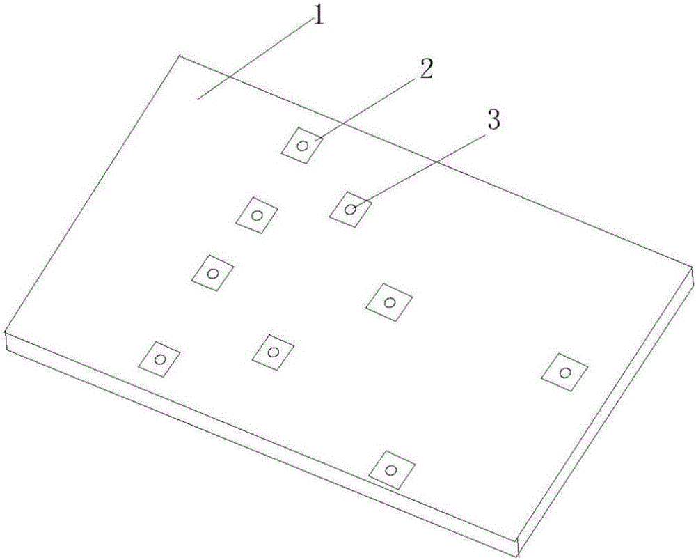
[0024] Such as figure 1 As shown, the detection and positioning platform of this embodiment includes a positioning platform 1 and a boss 2 located on the positioning platform. The boss 2 is provided with a threaded mounting hole 3. Three bosses form a group, and the number of boss groups can be three groups. , the lines connecting the centers of the three bosses in each group form an equilateral triangle, and the side lengths of the three formed equilateral triangles are different in size.

[0025] When positioning, the product to be tested having a through hole corresponding to the threaded mounting hole of the boss is installed on a group of bosses with an appropriate size in the positioning platform through bolts, and the positioning can be completed.

[0026] After the inspection work is completed, the fixing bolts are taken out, and the product to be inspected can be taken out, and the installation inspection of the next product is carried out.

Embodiment 2

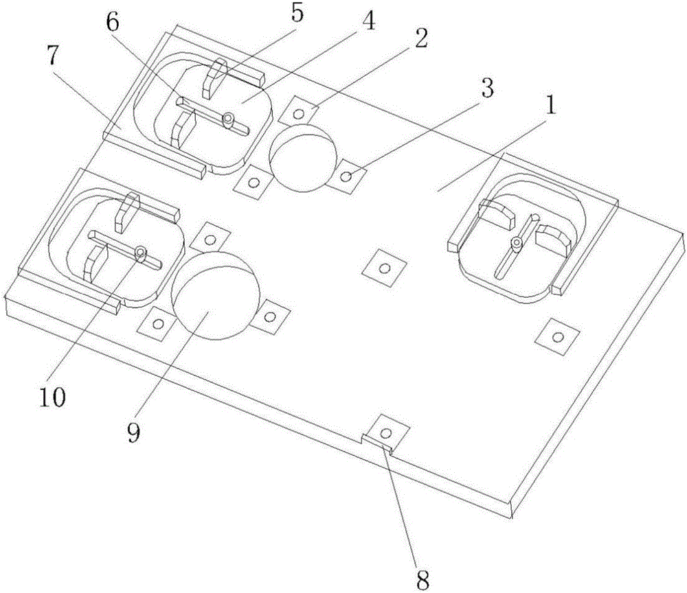
[0028] Such as figure 2 As shown, the detection and positioning platform of this embodiment also includes three positioning blocks 4 and three corresponding U-shaped chutes 7 on the basis of the first embodiment. The U-shaped chute 7 is matched, and the positioning block 4 is provided with a waist-shaped long through hole 6, and two threaded holes connected with the positioning block 4 are set on the positioning table 1, and the threaded holes are located at the sliding position of the waist-shaped long through hole 6. On the track, the positioning block 4 is connected to the positioning platform through the waist-shaped long through hole 6 using bolts. The tightness of the bolts ensures that the positioning block can slide back and forth in the U-shaped chute 7 on the positioning platform, and the bolt cap can ensure that the positioning block does not come out. U-shaped chute. The positioning block 4 may be provided with a hand-held block 5 for swinging the positioning blo...

Embodiment 3

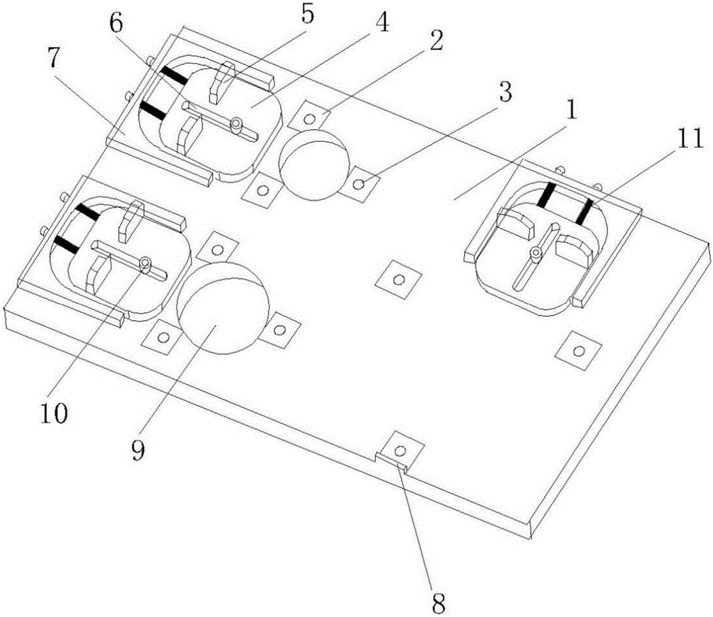
[0032] Such as image 3 As shown, the detection and positioning platform of this embodiment also includes a spring 11 and a bolt 13 on the basis of the second embodiment, the bottom end of the U-shaped chute 7 is provided with a through hole, and the positioning block 2 is provided with a The threaded hole 12 corresponding to the through hole, the bolt 13 passes through the through hole of the U-shaped chute, then passes through the inner hole of the spring 11, and finally directly connects to the threaded hole 12 of the positioning block 2.

[0033] The positioning block 2 is connected to the positioning platform through the slide rail bolt 13, and the slide rail bolt 13 is not fastened to ensure that the positioning block 2 can slide freely and smoothly in the U-shaped chute 7 of the positioning platform without falling out of the U-shaped chute 7, Such as Figure 5 As shown in the installation bolt-spring structure, the bolt passes through the through hole of the U-shaped ...


PUM


Abstract

The invention provides a rapid detection and locating platform comprising a locating mesa, a boss, a locating block and a U-shaped slide slot. The boss is arranged on the locating mesa. The boss is provided with an installing hole. The U-shaped slide slot is arranged on the locating mesa. The locating block can slide in the slide slot of the U-shaped slide slot and can be fixed at the required position. The boss is arranged at the open end of the U-shaped slide slot. The boss is parallel to the bottom end of the U-shaped slide slot, and one side away from the U-shaped slide slot is provided with a position limiting block. The position limiting block is a protrusion on the surface of the boss. The rapid detection and locating platform is simple in structural form, low in cost and diverse in form and can be suitable for detection of different products.

Description

technical field [0001] The invention provides a detection and positioning platform, and in particular relates to a rapid detection and positioning platform that can be applied to rapid batch detection and positioning work. Background technique [0002] In the field of inspection, most of the inspection work is carried out around batch products. The inspection work of batch products often has the characteristics of a large number of inspection products and consistent inspection schemes. In some structures with more complex structures and more inspection indicators, the single external interface is relatively regular. In the detection of optical lenses, etc., especially in the face of the use of semi-automatic detection equipment, such as three-coordinate measuring machines, large universal tool microscopes, etc., a platform for fast and accurate positioning of batch products is needed to solve repeated manual measurement and positioning. slow problem. Contents of the invent...

Claims


Application Information

Patent Timeline
Patent Type & Authority Applications(China)
IPC IPC(8): G01B21/00G01M11/00
CPCG01B21/00G01M11/00
Inventor 林上民胡丹丹王虎刘杰刘阳陈苏司慧琳刘美莹
Owner XI'AN INST OF OPTICS & FINE MECHANICS - CHINESE ACAD OF SCI
Why Eureka
Try Eureka