
Locking mechanism for a bone screw

a locking mechanism and bone screw technology, applied in the field of osteosynthesis holding systems, can solve problems such as deformation of snap catches and/or grooves

Inactive Publication Date: 2007-02-06
AESCULAP AG
View PDF34 Cites 17 Cited by
  • Summary
  • Abstract
  • Description
  • Claims
  • Application Information

AI Technical Summary

Benefits of technology

The present invention relates to a locking mechanism for securing a bone screw to a clamping element of an osteosynthesis holding system. The locking mechanism includes a clamping element with snap catches that interlock with a groove in the bone screw to secure the bone screw to the clamping element. The snap catches may have spikes that act as bone anchors. The invention provides a removal device for easy removal of the bone screw, as well as a method for revision of the bone screw. The technical effects of the invention include improved stability and secure locking of the bone screw to the clamping element, as well as easier removal and revision of the bone screw.

Problems solved by technology

Removal of the screw from the clamping element may result in deformation of the snap catches and / or the groove.

Method used


Image

  • Locking mechanism for a bone screw
  • Locking mechanism for a bone screw
  • Locking mechanism for a bone screw

Examples


Embodiment Construction

[0041]The ensuing detailed description provides preferred exemplary embodiments only, and is not intended to limit the scope, applicability, or configuration of the invention. Rather, the detailed description of the preferred exemplary embodiments will provide those skilled in the art with an enabling description for implementing a preferred embodiment of the invention. It should be understood that various changes may be made in the function and arrangement of elements without departing from the spirit and scope of the invention as set forth in the appended claims.

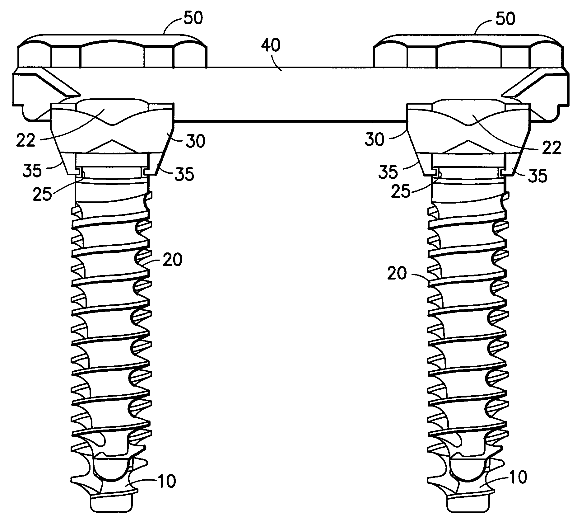
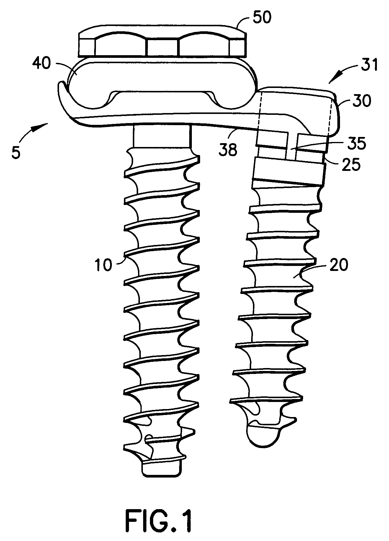
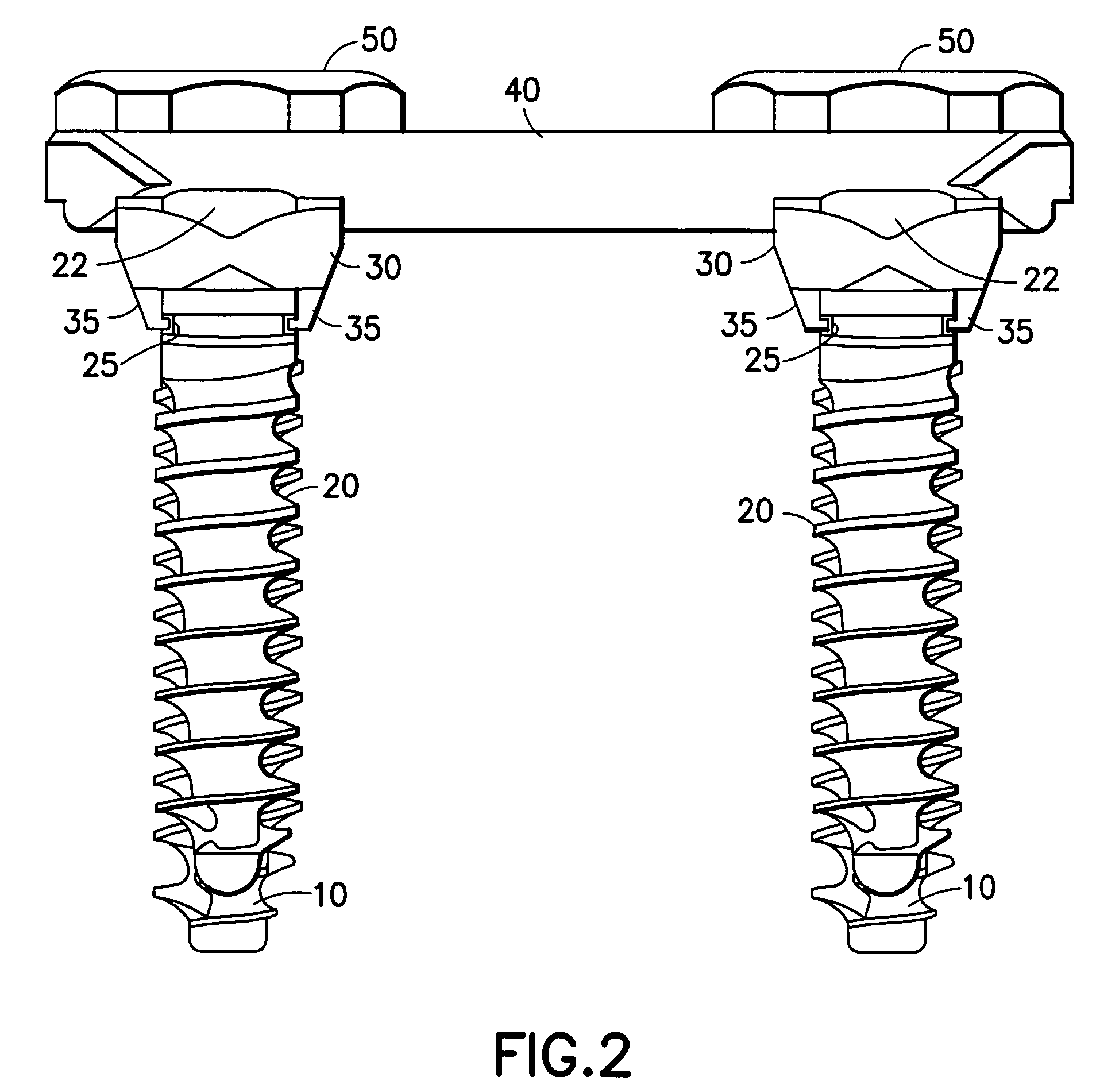
[0042]The present invention relates to a locking mechanism for securing a bone screw to a clamping element of an osteosynthesis holding system. An example embodiment of an osteosynthesis holding system with which the present invention can be implemented is described in detail in commonly assigned U.S. Pat. No. 6,206,879 entitled “Osteosynthetic Holding System.” Although the present invention will be described in connection...


PUM


Abstract

A locking mechanism for securing a bone screw 20 to a clamping element 30 of an osteosynthesis holding system 5 is provided. The bone screw 20 has a circumferential groove 25 located on a top portion of the screw 20 below a screw head 22. Snap catches 35 protrude from a bone-contacting surface 38 of the clamping element 30 and interlock with the groove 25 in the screw 20 when the screw 20 is inserted into the clamping element 30 (e.g., when the screw is screwed into a bone segment through a hole in the clamping element). A removal device 90 is provided for removing the screw 20, as a greater axial force is required to overcome the locking mechanism than is needed to engage the locking mechanism. A method for revision (removal) of the screw 20 from the locking mechanism is also provided.

Description

[0001]This application is a divisional of U.S. patent application Ser. No. 10 / 038,376 filed on Jan. 3, 2002 which application claims the benefit of U.S. provisional patent application No. 60 / 262,968 filed on Jan. 19, 2001.BACKGROUND OF THE INVENTION[0002]The present invention relates generally to osteosynthesis holding systems, such as those used for stabilization of the spinal column. In particular, a locking mechanism for securing a bone screw to a clamping element of an osteosynthesis holding system is provided. A removal device is provided for removing the bone screw, as a greater axial force is required to overcome the locking mechanism than is needed to engage the locking mechanism. A corresponding method for revision (removal) of the bone screw from the locking mechanism is also provided.[0003]It is well known that in osteosynthesis holding systems in general, and in those systems used for stabilization of the spinal column in particular, a loosening of the bone screw which s...

Claims


Application Information

Patent Timeline
Patent Type & Authority Patents(United States)
IPC IPC(8): A61B17/58A61F2/00A61B17/16A61B17/70A61B17/80A61B17/84A61B17/86A61B17/88A61B17/92A61B19/00
CPCA61B17/1671A61B17/1697A61B17/8047A61B17/8625A61B17/8888A61B17/92A61B17/7059A61B17/848A61B2017/8655A61B19/54A61B17/8605A61B90/39
Inventor BEGER, JENSZEPF, RUDOLFBEISSE, RUDOLFPOTULSKI, MICHAEL
Owner AESCULAP AG
Learn More