Ruggedized digital low-light viewing device

a digital low-light viewing and rugged technology, applied in the field of optical devices, can solve the problems of poor quality and/or limited user capabilities, low-light viewing devices for image intensification low-light viewing devices are not the current low-light viewing devices manufactured are neither affordable nor easily adapted to non-military use, etc., to achieve excellent low-light performance, reduce cost, and facilitate the effect of holding

Inactive Publication Date: 2007-02-06
XENONICS INC
View PDF15 Cites 13 Cited by
  • Summary
  • Abstract
  • Description
  • Claims
  • Application Information

AI Technical Summary

Benefits of technology

[0011]The present invention provides a low-light viewing device that is easy to hold with one hand and to operate, is waterproof, and provides excellent low-light performance with an integral telephoto zoom lens at a greatly reduced cost, can be assembled using off-the-shelf or custom parts that are easy to obtain or manufacture, thereby further reducing manufacturing cost, and utilizes passive imaging to reduce power supply consumption, aiding in reducing the size and weight of the assembly.
[0012]According to an aspect of the present invention, a low-light viewing device comprises a housing having a first end and an opposing second end, the first end defining an optical input aperture and the second end defining an optical output aperture; an infra-red camera assembly responsive to low intensity light and infra red energy received via the input aperture for generating an output image; a signal processor coupled to the camera assembly for processing the output image; a display assembly coupled to the camera assembly for displaying the processed image; a zoom lens assembly coupled to the camera assembly for electronically variably focusing the output image; and control electronics responsive to a control mechanism disposed on a surface of the housing for controlling operating functions of the low-light viewing device, the control mechanism navigable via a user's digit for controlling the operating functions. The assembly of the present invention enables a viewer to detect, recognize, identify and observe objects under low-light conditions at close range or at significant distances.
[0013]According to another aspect of the present invention, a handheld digital low-light viewing device comprises a protective housing having a first end and an opposing second end, the first end defining an optical input aperture and the second end defining an optical output aperture; the protective housing contoured to a user's hand, the housing containing: an infra-red camera assembly responsive to low intensity light and infra red energy received via the input aperture for generating an output image; a signal processor coupled to the camera assembly for processing the output image; a display assembly coupled to the camera assembly for displaying the processed image via the output aperture to a viewer; a zoom lens assembly coupled to the camera assembly for electronically variably focusing the output image; and control electronics responsive to a plurality of user-activatable switches disposed on a top surface of the housing and co-located within a region of the housing accessible via a single digit of a user during viewing via the device for controlling operating functions of the digital low-light viewing device. The assembly of the present invention further provides for still image and / or video capture of an object viewed by the assembly by means of a simple control mechanism or switch operatively coupled to the camera assembly and to the signal processor for capturing and processing the image data for storage and retrieval. Memory sufficient to store such image data is included within the assembly, and a mechanism is provided for downloading the stored or captured image data to a remote device (e.g. a printer, computer or other peripheral device), such as a USB port or other interface. The digital low-light viewing assembly of the present invention further includes software and / or hardware functionality for implementing control program functions and enabling user selection of certain program mode features associated with the low-light assembly.

Problems solved by technology

However, many of the present low-light viewing devices currently being manufactured are neither affordable nor easily adapted to non-military uses.
In recent years a number of low-light viewing devices have been introduced into the consumer market, but are often of poor quality and / or offer the user limited capabilities.
Image intensified low-light viewing devices tend to be very expensive and require sophisticated, heavy lenses to produce long range images.
Image intensified devices are also quite prone to damage if used in high-light situations.
This characteristic renders such products virtually useless in most urban areas.
Moreover, due to excessive cost, thermal imaging devices have not been widely accepted.
Most digital low-light viewing devices currently on the market utilize fixed-focus lenses which must be manually adjusted and are active devices, i.e., providing IR illumination to assist in detection, which causes the devices to consume power quickly.
The aforementioned devices are deficient in several respects, precluding practical use in both commercial arenas and by the military and law enforcement agencies.
Such devices tend to be both heavy and fragile, are unable to withstand the shock of impact and wear and tear caused by regular military or law enforcement use, and are easily permeated by water or moisture that can render them inaccurate or even unusable.
Additionally, such devices generally have fixed magnification that allow the user to detect objects, but lack variable magification capabilities that allow the user to recognize and identify objects once detected.
These devices also tend to have relatively short ranges, are bulky, are not ergonomic in design, and lack simplified user controls.
Moreover, such devices can be quite costly, often requiring proprietary components and elaborate assembly techniques, making them impractical for widespread military or law enforcement use.

Method used


Image

  • Ruggedized digital low-light viewing device
  • Ruggedized digital low-light viewing device
  • Ruggedized digital low-light viewing device

Examples


Embodiment Construction

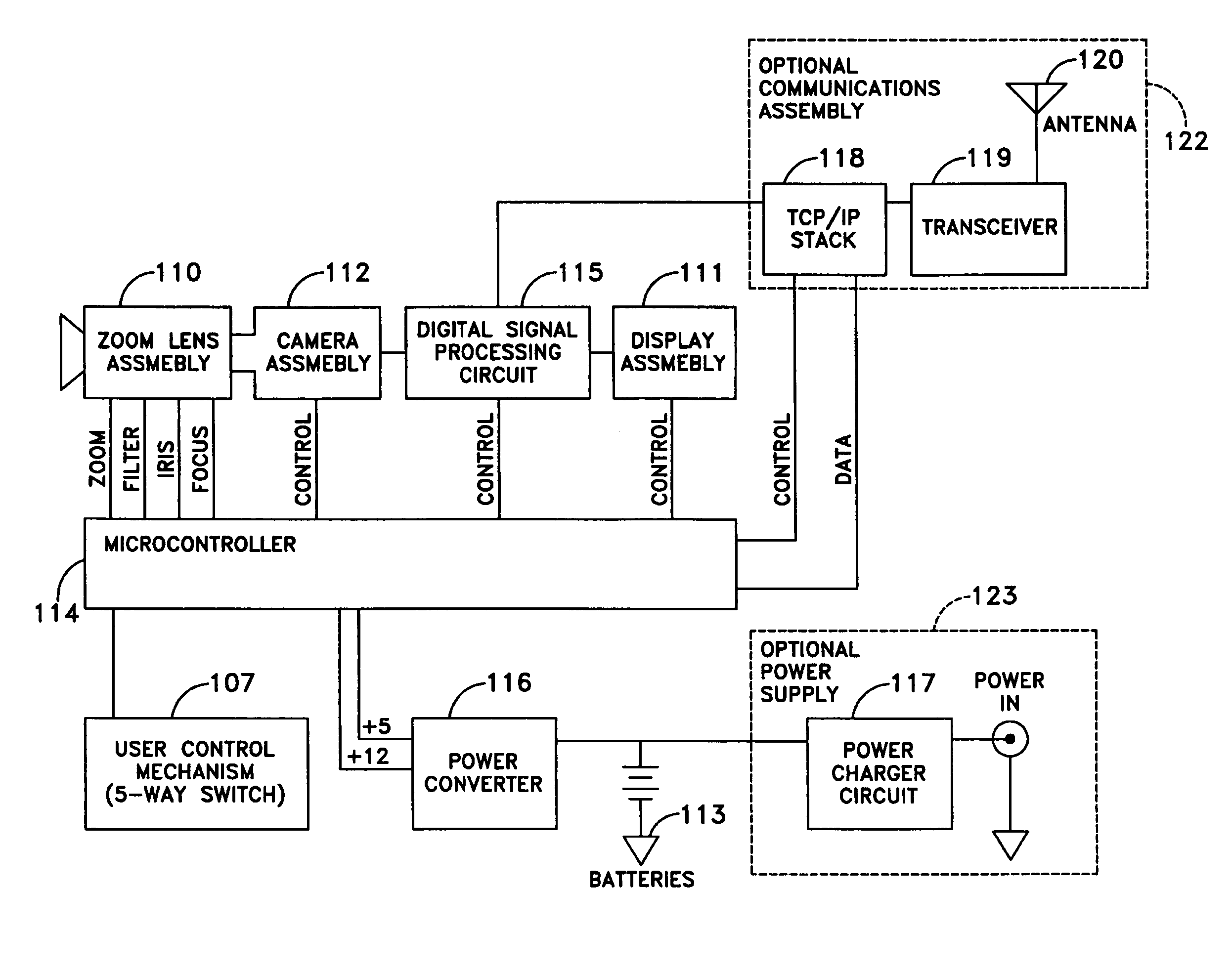
[0026]To address the problems of the prior art, the present invention provides a passive imaging ruggedized low-light viewing device capable of converting low-intensity visible light and infrared energy into a visible image. A digital low-light viewing assembly consistent with the present invention generally includes a low-light infrared camera having still / video image capture functionality, an LCD, OLED LCOS, CRT or plasma display and eyepiece lens, a zoom lens assembly, control electronics with one or more multi-position operator switches capable of being manipulated via a single digit of a user's hand while the device is being operated and the target viewed by the user, and standard batteries, all encased in an easily assembled waterproof housing, as will be described in further detail below.

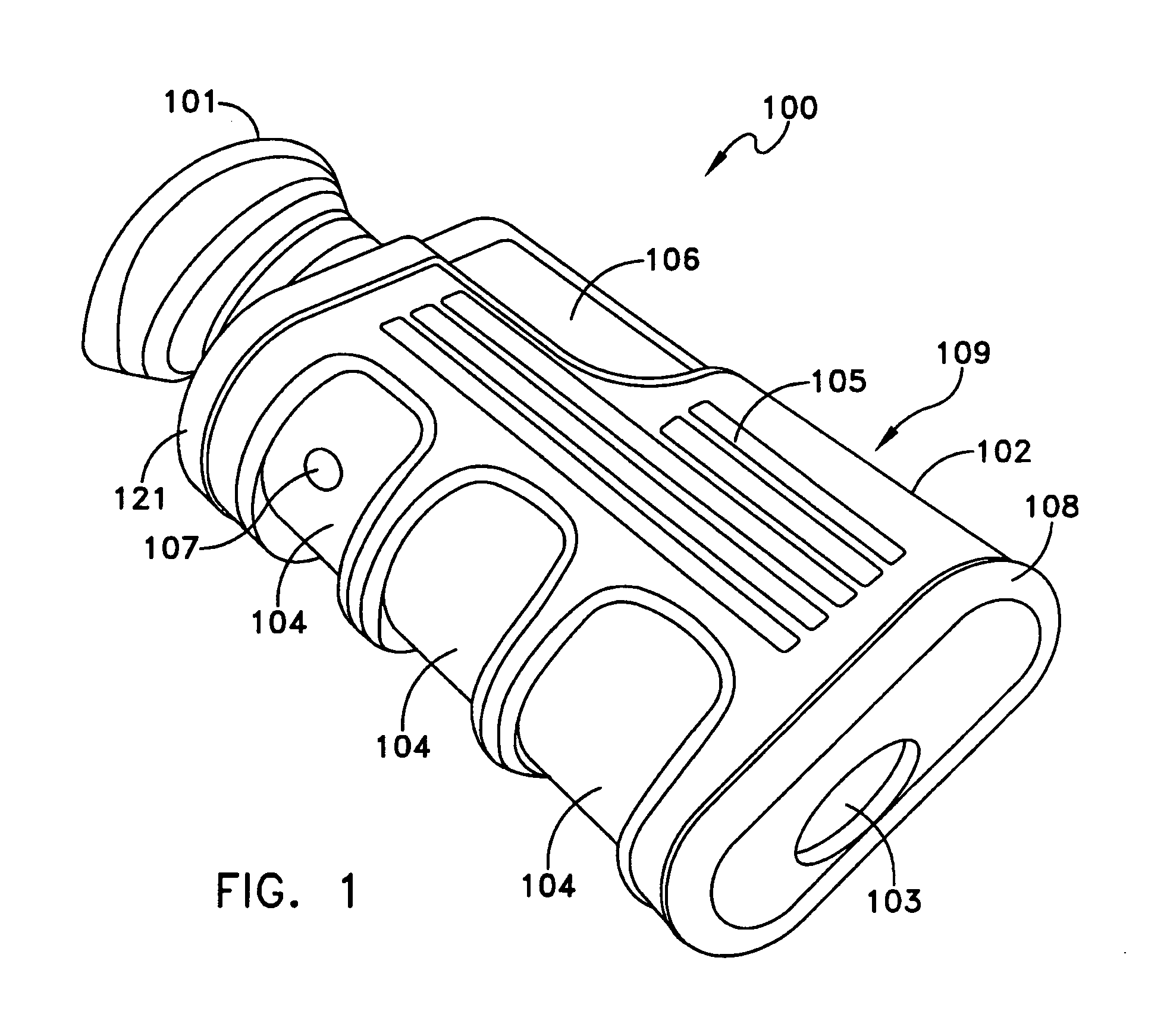
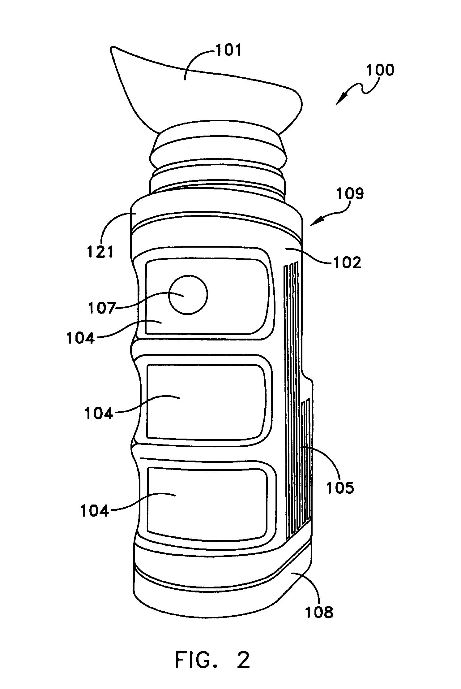
[0027]With reference now to FIGS. 1 through 6, various external views of an exemplary low-light vision assembly 100 consistent with one embodiment of the present invention are illustrated. As...


PUM


Abstract

A digital low-light viewing device comprises a housing having a first end and an opposing second end, the first end defining an optical input aperture and the second end defining an optical output aperture; an infra-red camera assembly responsive to low intensity light and infra red energy received via the input aperture for generating an output image; a signal processor coupled to the camera assembly for processing the output image; a display assembly coupled to the camera assembly for displaying the processed image; a zoom lens assembly coupled to the camera assembly for electronically variably focusing the output image; and control electronics responsive to a control mechanism disposed on a surface of the housing for controlling operating functions of the low-light viewing device, the control mechanism navigable via a user's digit for controlling the operating functions.

Description

RELATED APPLICATIONS[0001]This application claims priority to U.S. Provisional Application Ser. No. 60 / 621,415, filed Oct. 22, 2004, the subject matter thereof incorporated by reference herein in its entirety, and further claims priority to and is a continuation-in-part of U.S. patent application Ser. No. 11 / 060,903, filed on Feb. 18, 2005 entitled “Portable Long Range Searchlight With Telescopic Viewing and Imaging Systems”, the subject matter thereof incorporated by reference herein in its entirety.FIELD OF THE INVENTION[0002]The present invention relates generally to optical devices that enable a viewer to detect, recognize, identify and observe objects under low-light conditions, and more particularly, to a handheld, ruggedized digital low-light viewing system.BACKGROUND OF THE INVENTION[0003]Low-light viewing systems are widely used in the military to provide soldiers, aviators and sailors with the ability to view objects at night or during other low-light conditions. As a resu...

Claims


Application Information

Patent Timeline
Patent Type & Authority Patents(United States)
IPC IPC(8): G01J5/00G02B23/00
CPCG02B23/12H04N17/00G03B17/00F21L2/00G02B23/00
Inventor PALMER, GARYKENNEDY, JEFFREY
Owner XENONICS INC
Why Eureka
Try Eureka