
Multi-function integrated automation cable connector system and method

a multi-functional, automation cable technology, applied in the direction of switch power arrangement, power distribution line transmission, contact mechanism, etc., can solve the problems of increasing the number of conductors required, increasing the likelihood of problems, and increasing costs

Active Publication Date: 2007-02-06
ROCKWELL AUTOMATION TECH
View PDF9 Cites 22 Cited by
  • Summary
  • Abstract
  • Description
  • Claims
  • Application Information

AI Technical Summary

Benefits of technology

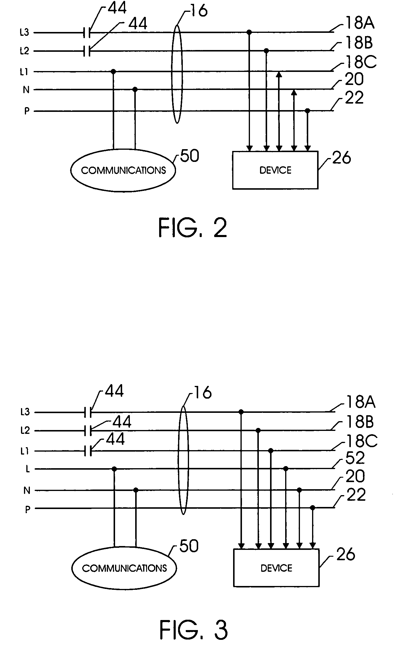
The present invention relates to power and data transfer assemblies and methods for transferring power and data to a device. The assemblies have three power conductors that can conduct three-phase power, and one or more additional conductors that can carry data signals and act as a neutral conductor. The assemblies can maintain one phase of three-phase power and data signals to a device even if one of the power conductors fails. The methods involve applying two phases of three-phase power to a device through the power conductors, and applying a third phase of three-phase power to the device through a separate conductor. The methods can also involve applying data signals to the device through the third conductor, which can be a neutral conductor, and using tap conductors to transfer the three-phase power to a second device. The invention allows for efficient and reliable transfer of power and data to devices.

Problems solved by technology

In turn, this may lead to increased costs with respect to both manufacturing and installation.
Moreover, the large number of conductors required increases the likelihood of a problem, such as a short, occurring in one of the wires.
This too may increase costs, particularly maintenance costs.
However, in many traditional networks, if an electrically upstream device is brought out of operation, then the electrically downstream devices, although functioning properly, may also be brought out of operation.
This may lead to undesired downtimes where repair perturbs overall operation of the entire installation.
This again may lead to increased costs both in manufacture and installation.
From time to time, problems may occur in certain devices of the network that require a total or partial shut down of the device or system.
In conventional networked systems, this may also lead to a loss of operating power, and even data, to the control devices connected to the load, such as relays, protective circuitry, sensing circuitry, actuators, controllers, drives, and so forth.
Without these power and data signals, it may be difficult for a technician to conduct diagnostic analysis of the component or system as a whole.
This can lead to increased repair and downtimes for both the system and the component.

Method used


Image

  • Multi-function integrated automation cable connector system and method
  • Multi-function integrated automation cable connector system and method
  • Multi-function integrated automation cable connector system and method

Examples


Embodiment Construction

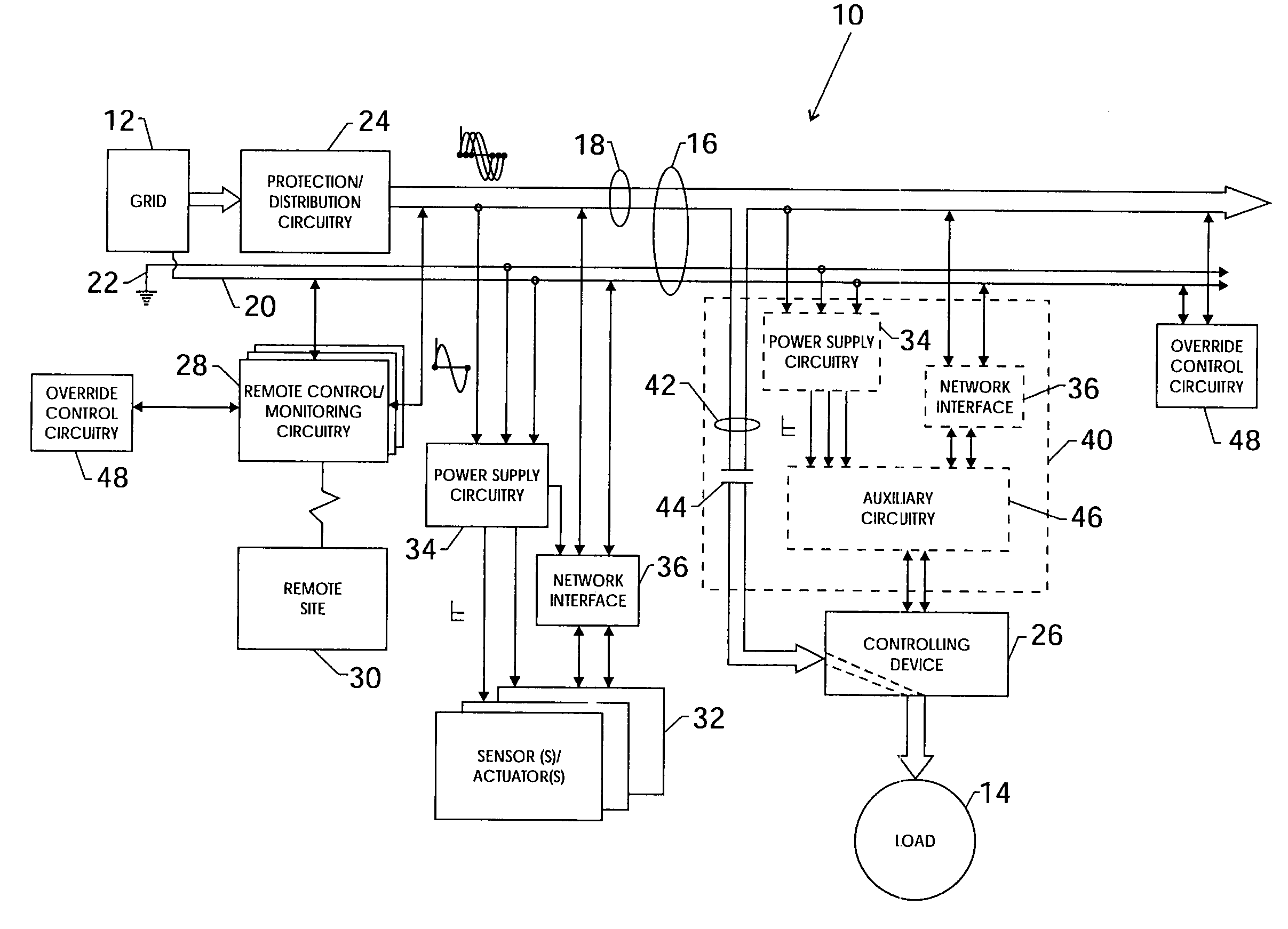
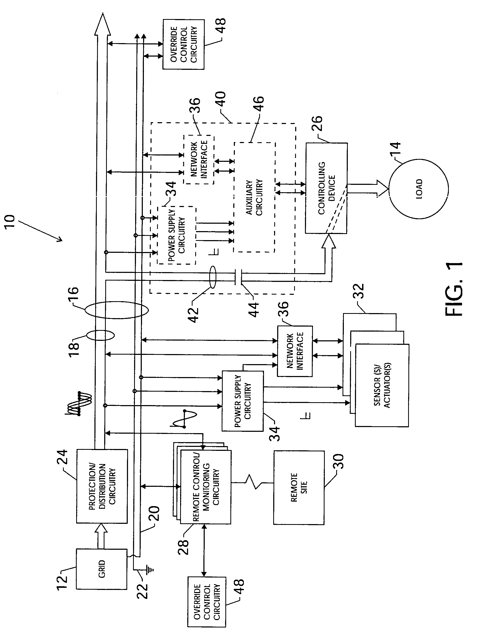
[0032]In industrial applications, efficient distribution of power and data signals is a motivating concern. Referring to FIG. 1, an exemplary section of a power and data distribution system 10 is presented. Although, for the purposes of explanation, the present embodiment relates to an industrial application, the present technique can be applied to any number of settings in which the efficient distribution of power and data is a concern. Returning to the present embodiment, the power and data distribution system 10 comprises a three-phase power source 12, such as a generator or power grid. The three-phase power may be ac power, such as 480V power, that powers a load 14. For example, the load 14 may be a motor that operates on three-phase 480 Vac power. For the present purposes, any voltage or current rating of ac power may be accommodated. Moreover, the power source 12 may be configured to provide other levels and kinds of power, such as 24 Vdc, along with the primary three-phase po...


PUM


Abstract

The present technique relates to a power and data signal transfer assembly including a plurality of conductors. Through the transfer assembly, power and data signals may be distributed and transferred to a wide variety of devices and locations. Moreover, in one example, power and data signals may be carried over a power conductor working in conjunction with a further conductor. In a further example, the assembly may include advantageous features, such as circuit protection circuitry and LEDs.

Description

FIELD OF THE INVENTION[0001]The present technique relates to power and data distribution within a networked system. More particularly, the present technique relates to distribution of both power and data signals over a power conductor.BACKGROUND OF THE INVENTION[0002]In a number of applications, networked systems require distribution of both power and data signals to and from any number of devices. For example, in industrial applications, a networked system may distribute power, typically three-phase power, as well as appropriate data signals to any number of locations. In traditional systems, power and data signals are transmitted over discrete wiring pathways. That is, power is distributed over dedicated power wires and data is distributed over dedicated data wires, both of which are disposed in separate protective conduits or cable jackets tubing.[0003]By way of example, networked control for a motor may require three wires for the transmission of three-phase power, one or more w...

Claims


Application Information

Patent Timeline
Patent Type & Authority Patents(United States)
IPC IPC(8): H04B3/54H02J13/00H02J3/00
CPCH02J13/002H02J13/0055Y10S307/01Y02E60/7815Y04S40/121Y02B90/2615H02J13/00007H02J13/00012Y02B90/20Y02E60/00
Inventor BRANDT, DAVID D.WIELEBSKI, WAYNE H.
Owner ROCKWELL AUTOMATION TECH
Learn More