Nuclear magnetic resonance apparatus

a technology of nuclear magnetic resonance and apparatus, which is applied in the direction of magnetic measurement, instruments, measurement devices, etc., can solve the problems of difficult to efficiently cover a sample, difficult to efficiently select the shape, and the noise of the coil caused by resistance can be reduced

Inactive Publication Date: 2007-02-06
HITACHI LTD
View PDF16 Cites 22 Cited by
  • Summary
  • Abstract
  • Description
  • Claims
  • Application Information

AI Technical Summary

Benefits of technology

[0016]If the probe coil is formed of superconducting material, a cooling mechanism is additionally required. A more detailed object of the present invention is to provide the configuration of an NMR apparatus provided with a cooling mechanism and the configuration of a probe for laterally inserting the probe, as well as applying a high-frequency magnetic field and receiving FID signals, with the following taken into account: thermal conduction cooling, electrical connection, and ease of construction.

Problems solved by technology

Especially, the enhancement of the sensitivity of probe coils (antenna elements) that receive signals is a technical challenge the solving of which is indispensable to NMR measuring apparatuses.
When a saddle or bird cage probe coil is formed of superconductor, especially, high-temperature superconductor to reduce the noise in the probe coil, the following problem arises: a superconducting film formed on a flat oxide single crystal substrate is utilized; therefore, the shape cannot be freely selected, and it is difficult to efficiently cover a sample.
Though the noise in the coil caused by resistance can be reduced, as a result, the following problem arises: reduction in the filling factor related to shape lowers the efficiency of application of high-frequency signals.
Therefore, if a solenoid probe coil is inserted into a conventionally used integral-type superconducting solenoid coil that generates a uniform magnetic field, a space in which a measurement sample is to be placed cannot be ensured.

Method used


Image

  • Nuclear magnetic resonance apparatus
  • Nuclear magnetic resonance apparatus
  • Nuclear magnetic resonance apparatus

Examples


first embodiment

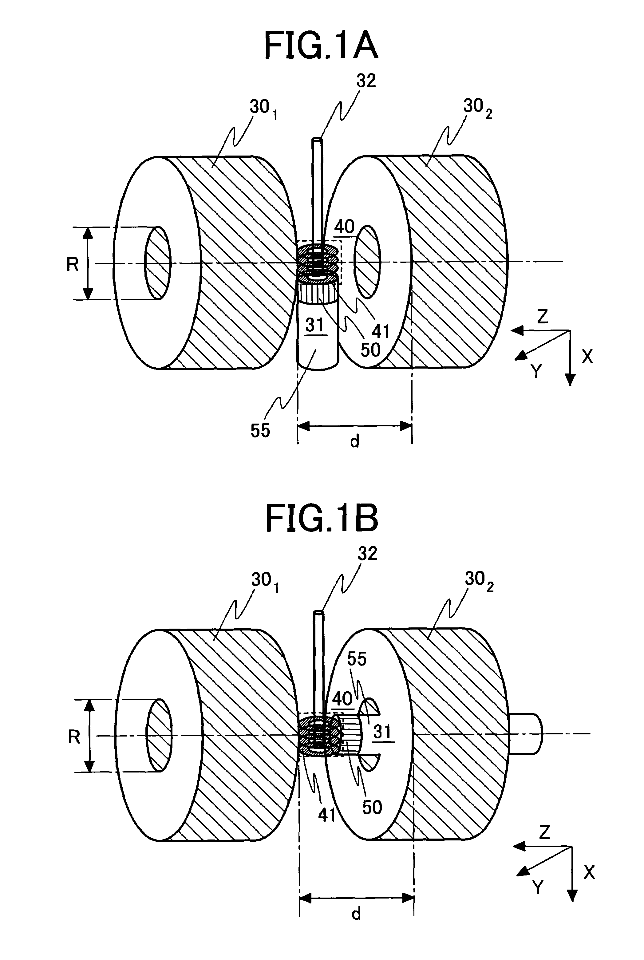
[0048](Example of Configuration in which a Cryo Probe 31 is Installed in the Direction Perpendicular to the Static Magnetic Field)

[0049]To carry out NMR measurement in the high-frequency band ranging from 300 MHz to over 1 GHz, the construction and mounting of the following solenoid coil were considered: a sample, 3 to 10 mm in diameter and 5 to 10 mm in length, is taken as a measuring object. The solenoid coil using a superconducting thin film is used to apply a magnetic field to the sample placed in the sample tube 32 and to receive free induction decay (FID) signals.

[0050]FIG. 4 is a side view illustrating a cryo probe 31 so constructed that the cryo probe 31 is installed in the direction perpendicular to the static magnetic field. The figure illustrates the cryo probe with one side face of a fixed substrate 72 for thermal conduction of sapphire removed. FIG. 5 is a sectional view taken along the line B—B (at the center of a hole 100 into which a sample tube 32 is to be passed) o...

second embodiment

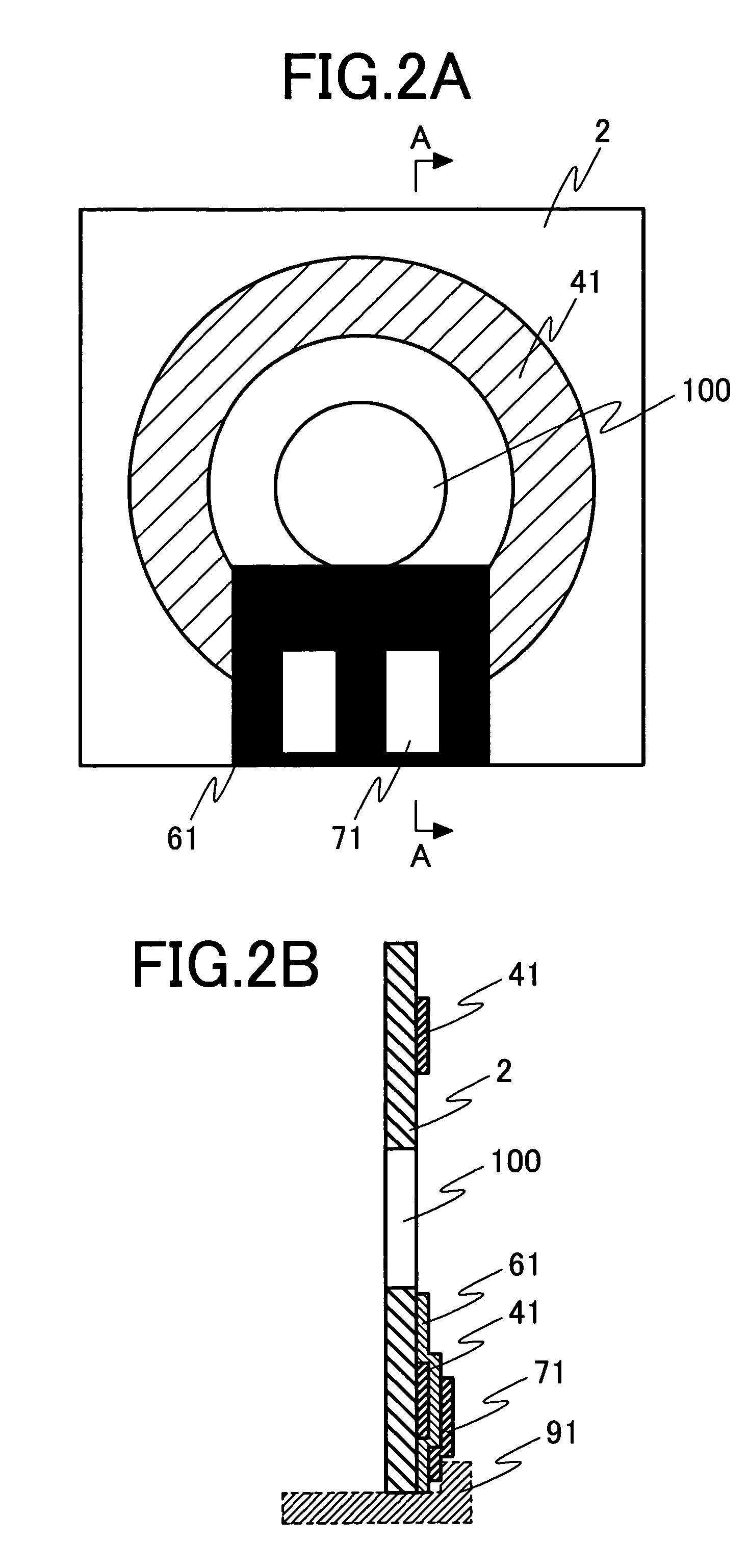
[0060](Example of Configuration in which a Cryo Probe 31 is Installed in the Direction Perpendicular to the Static Magnetic Field)

[0061]FIG. 6A is a top view of a transmission coil formed of an oxygen free copper thin film. FIG. 6B is a sectional view taken along the line C—C of FIG. 6A, as viewed in the direction of the arrows. Numeral 2 denotes a sapphire substrate, and 95 and 95′ denote oxygen free copper thin films. The oxygen free copper thin film 95 is formed on the sapphire substrate 2 in the same manner as of the reception coil. After the formation of the oxygen free copper thin film 95, the substrate 2 is perforated to form a hole 100 through which a sample tube 32 is to be passed. The hole in the substrate is formed by laser light irradiation. Numerals 921 and 922 denote wires described later.

[0062]FIG. 7 is a drawing roughly illustrating the configuration of a probe coil 40 formed by combining transmission coils and reception coils. The oxygen free copper thin films 95 an...

third embodiment

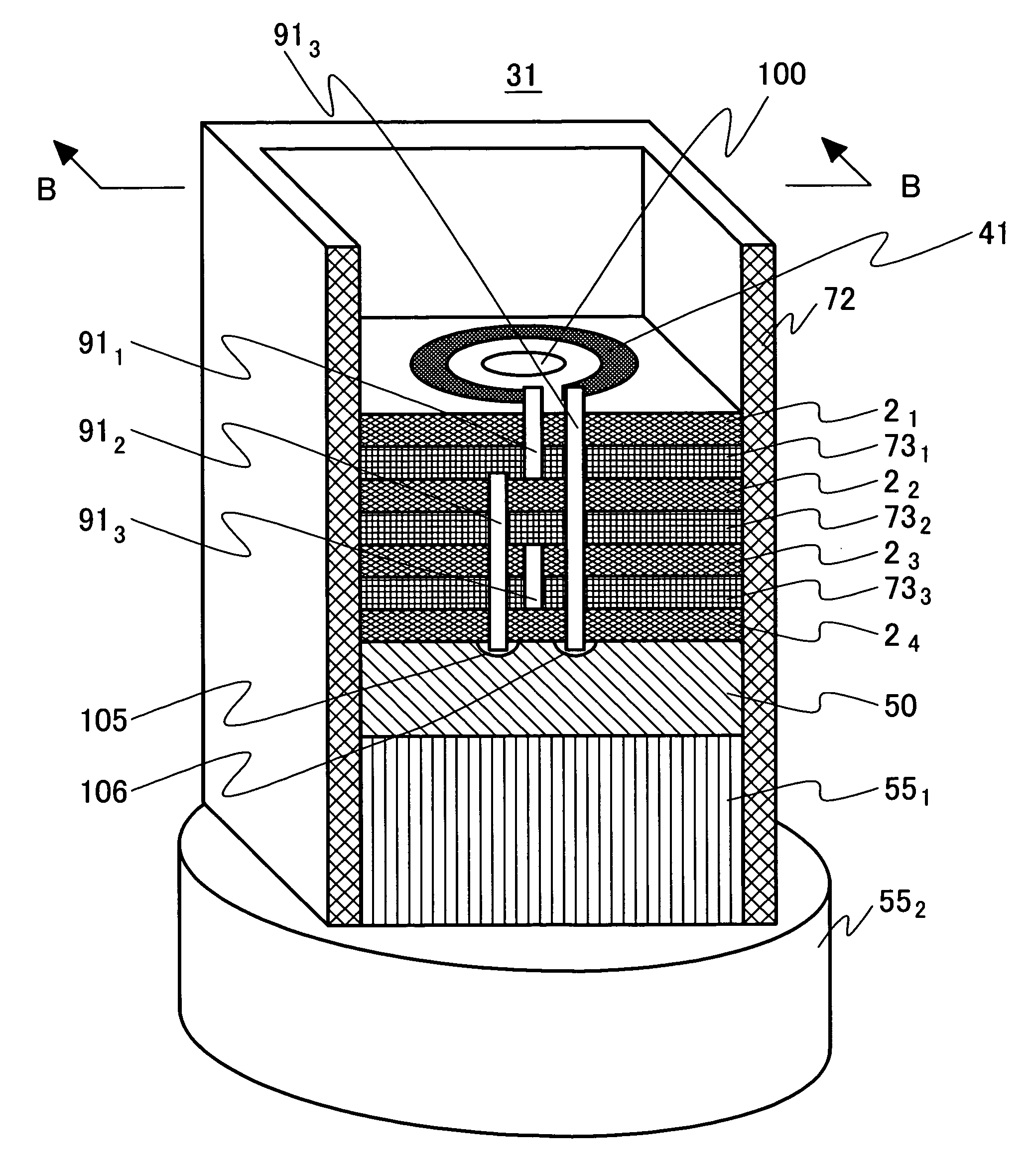
[0071](Example of Configuration in Which a Cryo Probe 31 is Installed in Parallel with the Static Magnetic Field)

[0072]FIG. 10A is a perspective view illustrating a probe coil 40 with a cryo probe 31 installed in parallel with the static magnetic field. FIG. 10B is a sectional view taken along the line D—D (at the center of an area where spacer substrates 73 are inserted into a cold head 50) of FIG. 10A, as viewed in the direction of the arrows.

[0073]The configuration of the cryo probe 31 illustrated in FIGS. 10A and 10B is essentially the same as that of the probe coil 40 illustrated in FIG. 4 with respect to portions related to the layered structure of the spacer substrates 73 and the substrates 2. In this construction in FIG. 10, however, the substrate 24 is not laminated on the upper face of the cold head 50. Therefore, a spacer substrate 735 for transferring cold to the substrate 24 is added to the lower face of the substrate 24. A substrate 23 of sapphire is disposed on the up...


PUM


Abstract

A configuration of an NMR apparatus is provided. In the NMR apparatus, a magnetic field space of higher uniformity is generated by split superconducting magnets. At the same time, it is provided with a cryo probe excellent in cooling capability and sensitivity between two superconducting solenoid coils constructed in very close proximity to each other. For this purpose, a probe coil provided between the two superconducting solenoid coils is so constructed that the following is implemented: a certain distance is ensured between a substrate with a coil formed thereon and another, and the substrates and spacer substrates for cooling are alternately laminated. The spacer substrates are cooled by a cold head of sapphire. When the probe coil is inserted in the same direction as a sample tube (direction perpendicular to the static magnetic field), the spacer substrates cannot be coupled directly by the cold head of sapphire. Therefore, they are cooled through a fixed substrate for thermal conduction of sapphire coupled with the cold head.

Description

CLAIM OF PRIORITY[0001]The present application claims priority from Japanese application JP2004-234319 filed on Aug. 11, 2004, the content of which is hereby incorporated by reference into this application.FIELD OF THE INVENTION[0002]The present invention relates to a nuclear magnetic resonance apparatus (hereafter, represented as “NMR apparatus”), and more particularly to an NMR apparatus characterized in the shape of a probe coil for transmitting a high-frequency signal to a sample placed in a predetermined uniform magnetic field (B0) with a predetermined resonance frequency and / or receiving a free induction decay (FID) signal and its construction for mounting.BACKGROUND OF THE INVENTION[0003]Nuclear magnetic resonance (NMR) measurement can be implemented by measuring response signals from atomic spins that constitute substances. The NMR measurement is an ultimate measuring technique that makes it possible to obtain microscopic information about substances. The basic principle beh...

Claims


Application Information

Patent Timeline
Patent Type & Authority Patents(United States)
IPC IPC(8): G01V3/00
CPCG01R33/34069G01R33/34053G01R33/34007G01R33/34023G01R33/34092
Inventor SAITOH, KAZUOHASEGAWA, HARUHIROYAMAMOTO, HIROYUKIOCHI, HISAAKIWAKUDA, TSUYOSHIOKADA, MICHIYA
Owner HITACHI LTD
Why Eureka
Try Eureka