Wobbling signal demodulation method, wobbling signal demodulation circuit, and optical disk drive

a wobbling signal and demodulation circuit technology, applied in the direction of digital signal error detection/correction, instruments, recording signal processing, etc., can solve the problems of increasing cost, achieve high speed without increasing cost, and fast and precisely demodulate a wobbling signal

Inactive Publication Date: 2007-02-06
RICOH KK
View PDF12 Cites 6 Cited by
  • Summary
  • Abstract
  • Description
  • Claims
  • Application Information

AI Technical Summary

Benefits of technology

[0013]A first specific object of the present invention is to provide a wobbling signal demodulation method and a wobbling signal demodulation circuit capable of fast and precisely demodulating a wobbling signal obtained based on light reflected from a recording surface of an optical disk without increasing cost of the circuit.
[0014]A second specific object of the present invention is to provide an optical disk drive capable of recording on the optical disk at a high speed without increasing the cost.
[0017]Because in the second step, sampling can be performed twice in each wobbling period to generate the digital signal, it is possible to greatly reduce the number of times of sampling when converting an analog signal to a digital signal. Therefore, it is possible to perform precise modulation of the wobbling signal during high-speed recording even when the common devices in the related art are used. That is, it is possible to at high speed and precisely demodulate the wobbling signal obtained based on light reflected from the optical disk without increasing cost of the circuit.
[0020]Because in the integration signal generation circuit, sampling can be performed twice in each wobbling period to generate the digital signal, it is possible to greatly reduce the number of times of sampling when converting an analog signal to a digital signal. Therefore, it is possible to perform precise modulation of the wobbling signal in high speed recording even when the common devices in the related art are used. That is, it is possible to quickly and precisely demodulate the wobbling signal obtained based on light reflected from the optical disk without increasing cost of the circuit.

Problems solved by technology

In order to meet this requirement, a fast AD converter is needed and this causes an increased cost.

Method used


Image

  • Wobbling signal demodulation method, wobbling signal demodulation circuit, and optical disk drive
  • Wobbling signal demodulation method, wobbling signal demodulation circuit, and optical disk drive
  • Wobbling signal demodulation method, wobbling signal demodulation circuit, and optical disk drive

Examples


Embodiment Construction

[0046]Below, preferred embodiments of the present invention are explained with reference to the accompanying drawings.

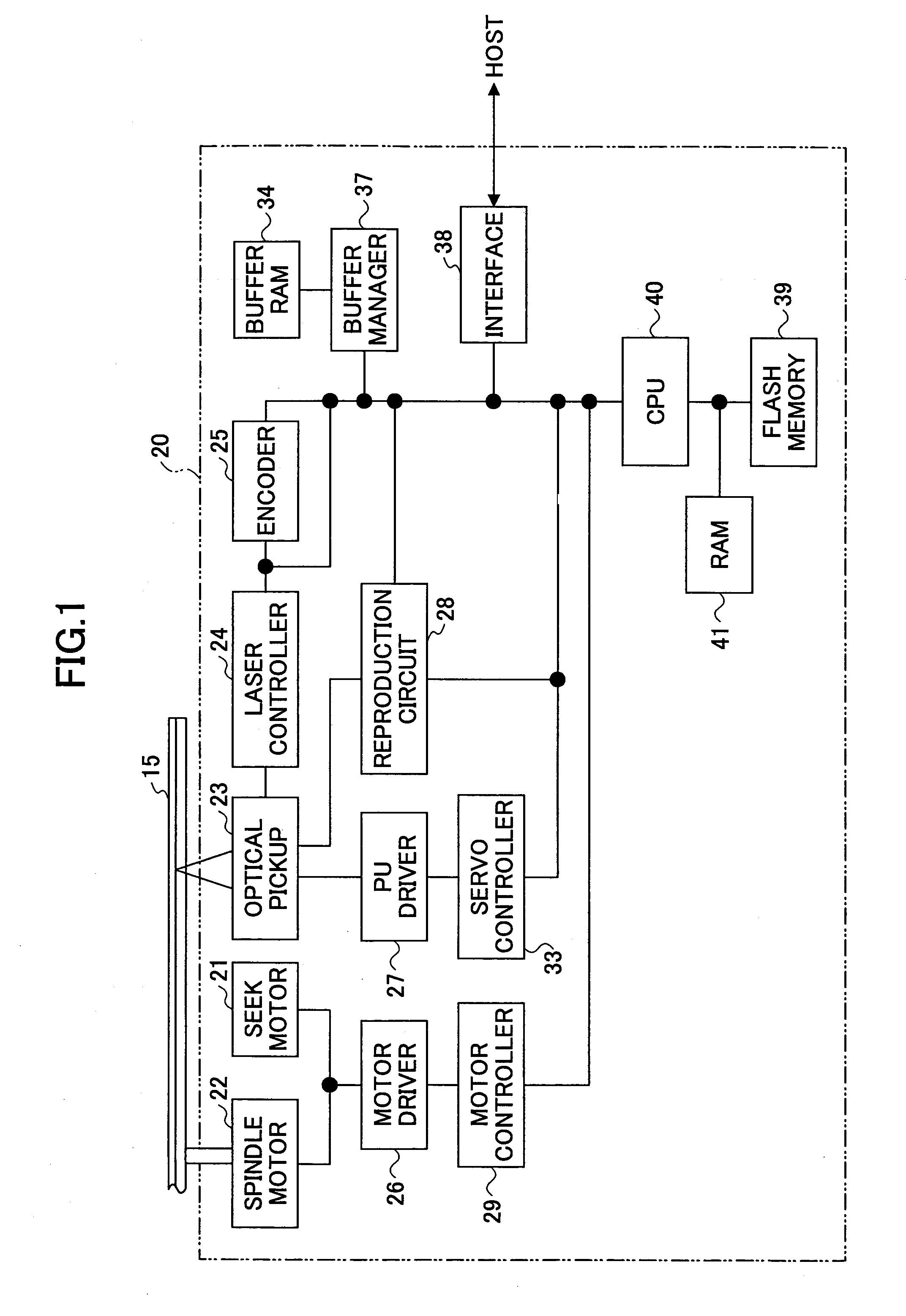
[0047]FIG. 1 is a block diagram schematically showing a configuration of an optical disk drive 20 according to an embodiment of the present invention.

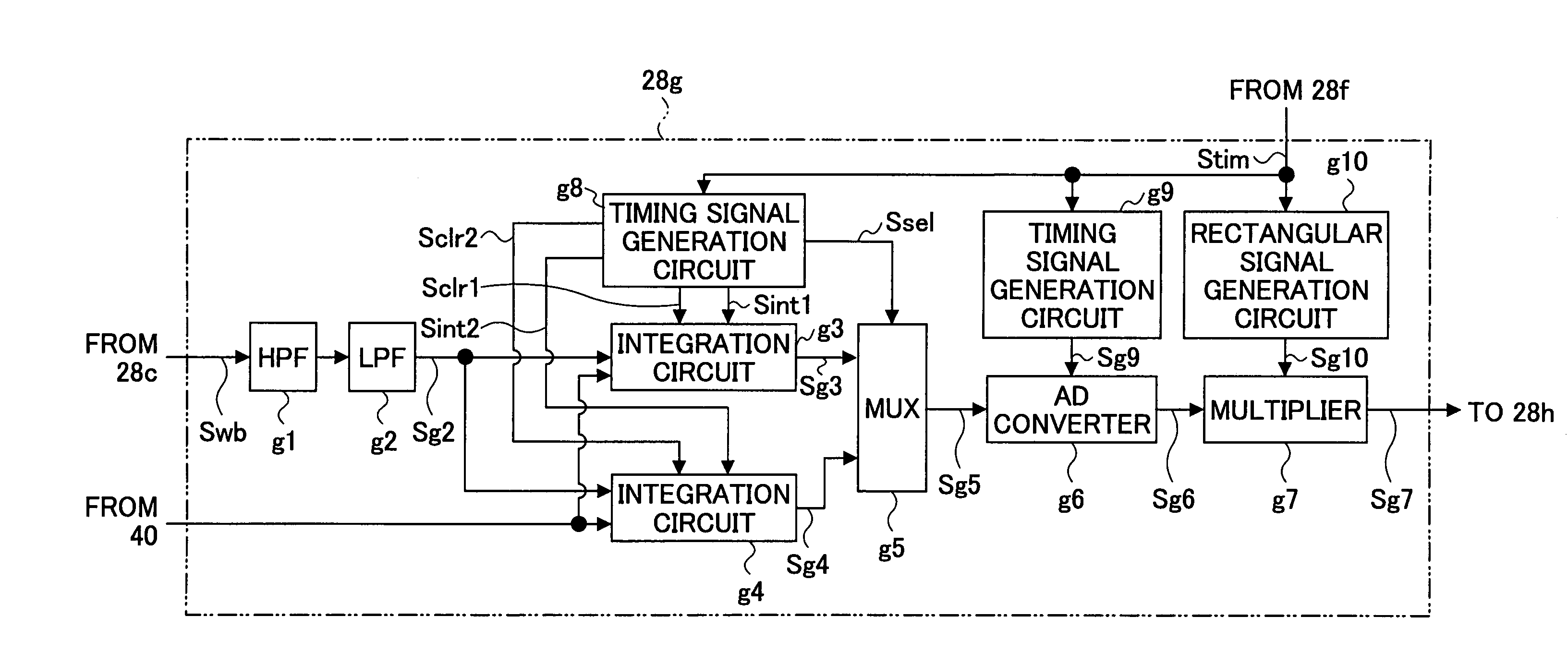
[0048]The optical disk drive 20 illustrated in FIG. 1 includes a seek motor 21, a spindle motor 22, an optical pickup 23, a laser controller 24, an encoder 25, a motor driver 26, a PU driver 27, a reproduction signal processing circuit 28, a motor controller 29, a servo controller 33, a buffer RAM 34, a buffer manager 37, an interface 38, a flash memory 39, a CPU 40, and a RAM 41.

[0049]In FIG. 1, the connection lines between the above elements just indicate the chief connection relation of them for typical signals and data, but do not indicate all connection relations in the optical disk drive 20.

[0050]As illustrated in FIG. 1, the optical disk drive 20 records or reproduces data in an optical disk 15. In this embodimen...


PUM

PropertyMeasurementUnit
wavelengthaaaaaaaaaa

Abstract

A wobbling signal demodulation method is disclosed that is capable of fast and precisely demodulating a wobbling signal without increasing cost of the circuit. The wobbling signal is obtained based on light reflected from a recording surface of an optical disk having a wobbling track formed thereon, and includes a carrier portion having a predetermined basic period and a phase demodulated wave portion including predetermined information. The wobbling signal demodulation method includes a first step of respectively integrating a portion of the wobbling signal corresponding to a first half of the basic period and a portion of the wobbling signal corresponding to a second half of the basic period in synchronization with a clock signal generated from the carrier portion; a second step of generating a digital signal based on a first integration result corresponding to the first half of the basic period and a second integration result corresponding to the second half of the basic period; and a third step of performing a phase demodulation on the phase demodulated wave portion of the wobbling signal based on the digital signal and the clock signal.

Description

CROSS-REFERENCE TO RELATED APPLICATION[0001]This application is a U.S. continuation application filed under 35 USC 111(a) claiming benefit under 35 USC 120 and 365(c) of PCT application JP2004 / 005790, filed on Apr. 22, 2004, which claims priority to Japanese patent application No. 2003-350633, filed in Japan on Oct. 9, 2003. The foregoing applications are hereby incorporated herein by reference.BACKGROUND OF THE INVENTION[0002]1. Field of the Invention[0003]The present invention relates to a wobbling signal demodulation method, a wobbling signal demodulation circuit, and an optical disk drive; and particularly, a wobbling signal demodulation method and a wobbling signal demodulation circuit for demodulating a wobbling signal obtained based on light reflected from a recording surface of an optical disk, and an optical disk drive having the wobbling signal demodulation circuit.[0004]2. Description of the Related Art[0005]Along with progress in digital technology and data compression t...

Claims


Application Information

Patent Timeline
Patent Type & Authority Patents(United States)
IPC IPC(8): G11B7/005G11B5/09G11B20/14G11B20/10G11B27/24
CPCG11B7/0053G11B27/24G11B2220/257G11B2220/218
Inventor ARAI, KUNIAKI
Owner RICOH KK
Why Eureka
Try Eureka