
Integrated business system for the design, execution, and management of projects

a business system and integrated technology, applied in the field of system for designing, constructing and managing the construction of a physical entity, can solve the problems of inefficient communication between the various team members, complicated specifications of interior designers and/or collaborating engineers, etc., and achieve the effect of facilitating information transfer

Inactive Publication Date: 2007-02-06
IBM CORP
View PDF87 Cites 78 Cited by
  • Summary
  • Abstract
  • Description
  • Claims
  • Application Information

AI Technical Summary

Benefits of technology

The present invention provides a method and system for creating a central database of information related to the design and construction of a building. This system allows remote computer systems to store or modify design information, and to communicate with each other and with business rules to manage changes on a project. The system also allows for information transfer between different computer systems. The technical effect of this invention is to provide a more efficient and organized way of managing the design and construction of buildings, which can save time and reduce errors.

Problems solved by technology

At any point during the project, revisions to the original architectural design specifications and drawings may occur which, in turn, may complicate the specifications of the interior designers and / or collaborating engineers.
While these existing architecture, engineering and construction software systems aid individual construction project team members, communication between the various team members remains as inefficient as in the past.

Method used


Image

  • Integrated business system for the design, execution, and management of projects
  • Integrated business system for the design, execution, and management of projects
  • Integrated business system for the design, execution, and management of projects

Examples


Embodiment Construction

)

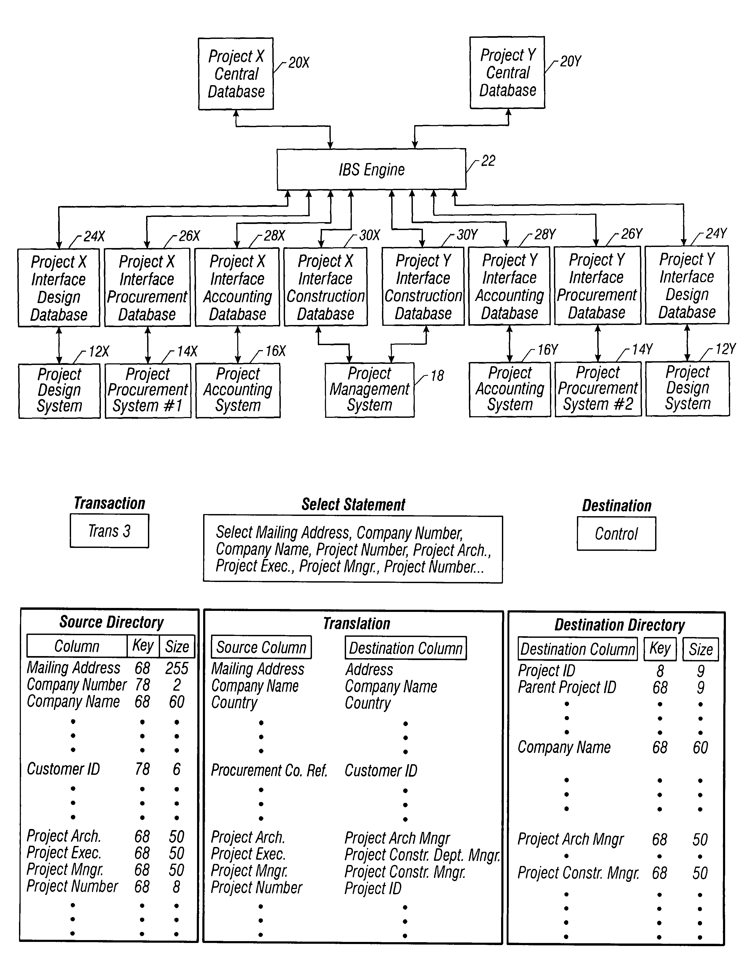
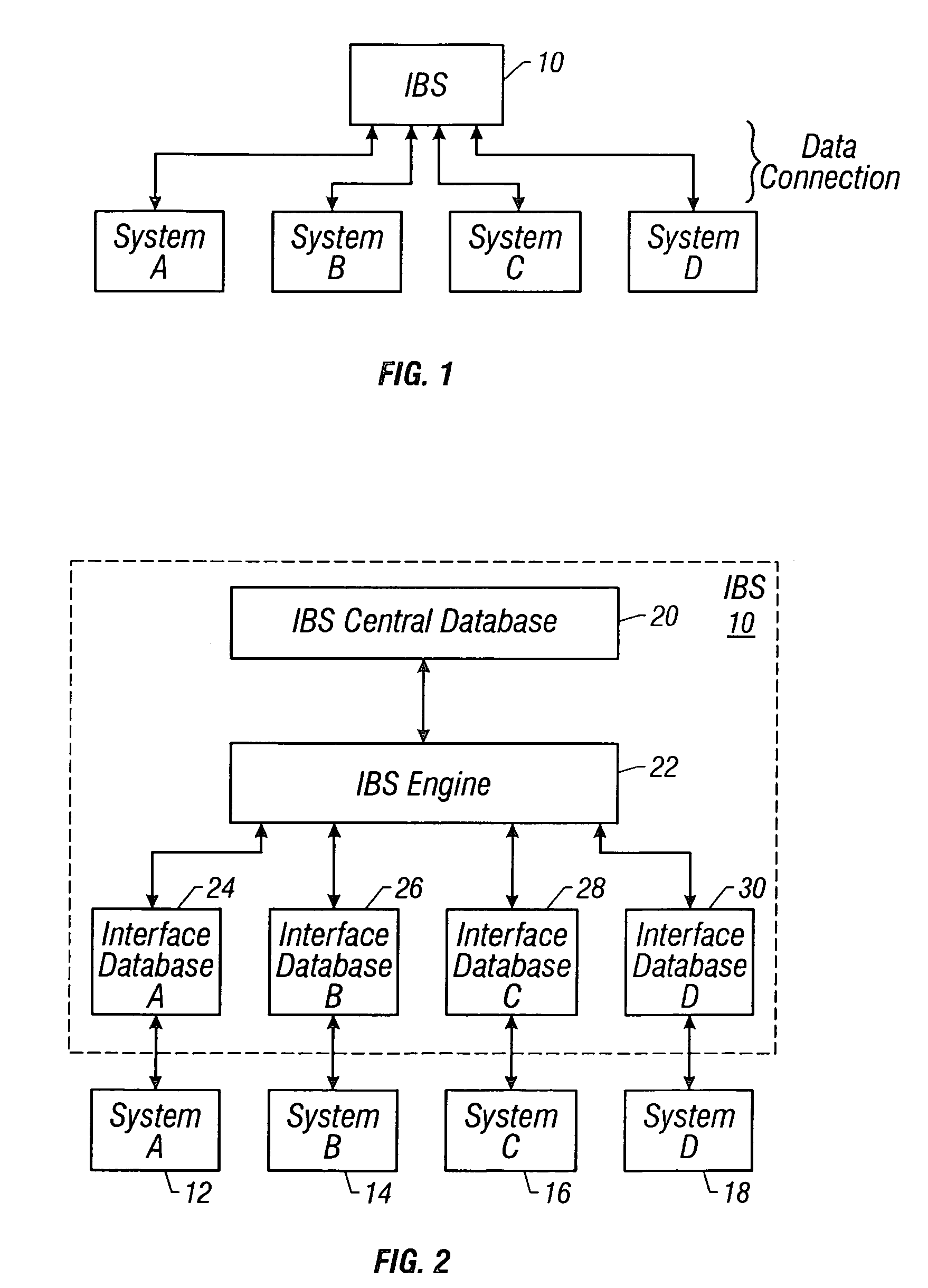
[0022]FIG. 1 illustrates an Integrated Business System (IBS) 10 implementing the present invention. In the embodiment shown in FIG. 1, the IBS is coupled to or in data communication with additional computer systems A through D via a data link, for example an Internet data link, to enable remote communication between the IBS and computer systems A through D. It is to be understood, however, that the present invention may enable communication between the IBS and computer systems A through D via a local or intranet data link. Computer systems A through D run distinct software tools that, without the IBS, are incapable of effectively communicating with each other.

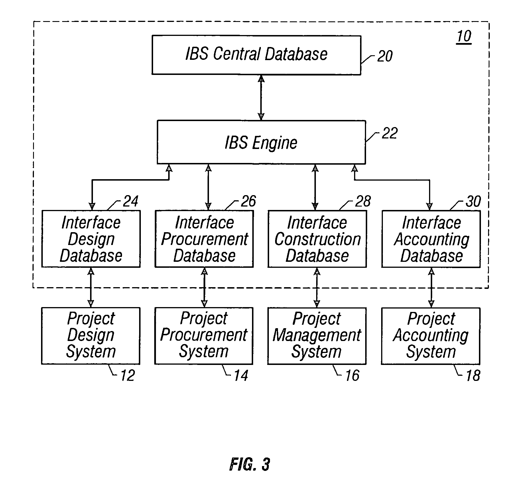
[0023]FIG. 2 shows one embodiment of the IBS 10 of FIG. 1. More particularly, the IBS shown in FIG. 2 includes an IBS central database 20 in data communication with an IBS engine 22 running on a host computer system which, in turn, is in data communication with IBS interface databases 24 through 30. IBS interface databases 24 ...


PUM


Abstract

The system of method for building a database for the design and execution of projects is described. This system includes a host computer system in data communication with a central database and at least first and second databases. The central data base stores information relating to the design and execution of the project predetermined to be important to one or more project team members. The first and second databases are in communication with first and second computer systems which may be remotely located from each other and which execute standard industry software tools. The host computer system is configured to monitor a plurality of transactions to the first database. Each of the plurality of transactions stores data in the first database. The monitoring includes comparing the plurality of a transaction against a predetermined transaction. If the host computer detects a match between one of the plurality of transactions and the predetermined transaction, the host computer reads the first data stored in the first database by the matched transaction and stores the first data in either the second database or the central database, or both. Additionally, the host computer system generates a message indicating that the first database was updated with the first data. This message is then transmitted to the second computer system.

Description

BACKGROUND OF THE INVENTION[0001]1. Field of the Invention[0002]The present invention relates to a system for designing, constructing and managing the construction of a physical entity such as a building. More specifically, the present invention relates to a system that facilitates a real time project database in data communication with several industry available software tools used in the design, execution and management of a physical entity such as a building.[0003]2. Description of the Related Art[0004]Many industries employ a team of players to design and execute a project. For example, the construction industry employs a team of players to design and construct a building, such as an office building, a hotel / casino, or a manufacturing facility. Typically, the project team includes architects who prepare architectural drawings and specifications of the project according to a developer's direction. The team also includes engineers who are responsible for building systems such as s...

Claims


Application Information

Patent Timeline
Patent Type & Authority Patents(United States)
IPC IPC(8): G06F17/00G06F17/30G06Q10/10
CPCG06F17/30575G06F17/5004G06Q10/10Y10S707/99942Y10S707/99943Y10S707/99945G06F16/27G06F30/13
Inventor WUCHERER, TOMNISBET, TODDNICASTRO, CHERISSE M.MARNELL, II, ANTHONY A.
Owner IBM CORP
Learn More