Modular, adjustable display rack

a display rack and module technology, applied in the field of adjustable display racks, can solve the problems of difficult adjustment of individual shelves on past display racks, limited location, ease, etc., and past displays have offered no assistance in ensuring the effect of display

Active Publication Date: 2007-02-13
ALTRIA GRP DISTRIBUTION
View PDF40 Cites 118 Cited by
  • Summary
  • Abstract
  • Description
  • Claims
  • Application Information

AI Technical Summary

Benefits of technology

[0011]The display stand of the present invention provides a number of advantages over prior display stands. The display stand of the present invention can be configured in virtually an unlimited number of different manners so that users of the display stand can individually tailor it to their own specifications. This individual tailoring includes the selection and placement of different types of shelves, the selection and placement of cabinets, signs, lights, product dispensers, literature dispensers, and other items that may be incorporated into the display stand. Once a given configuration of the display stand has been chosen and implemented, changes to this configuration can be made quickly and easily, if desired. Additionally, the slots on the back wall of the display stand and the inserts on the shelves, and other items, may be shaped in a nonstandard manner so that conventional shelving may not fit into the slots, thereby discouraging retailers from using the display stand to display other types of products. These and other advantages of the present invention will be apparent to one skilled in the art from the following specification when read in conjunction with the accompanying drawings.

Problems solved by technology

These past displays have also been limited in the location, arrangement, and ease of re-arrangement of the advertising and signs that accompany the display and which help to sell the products stored thereon.
The individual shelves on past display racks have also often been difficult to adjust without removing the surrounding shelves.
Past displays have offered no assistance in ensuring that retailers did not use the displays to promote other manufacturer's products.

Method used


Image

  • Modular, adjustable display rack
  • Modular, adjustable display rack
  • Modular, adjustable display rack

Examples


Embodiment Construction

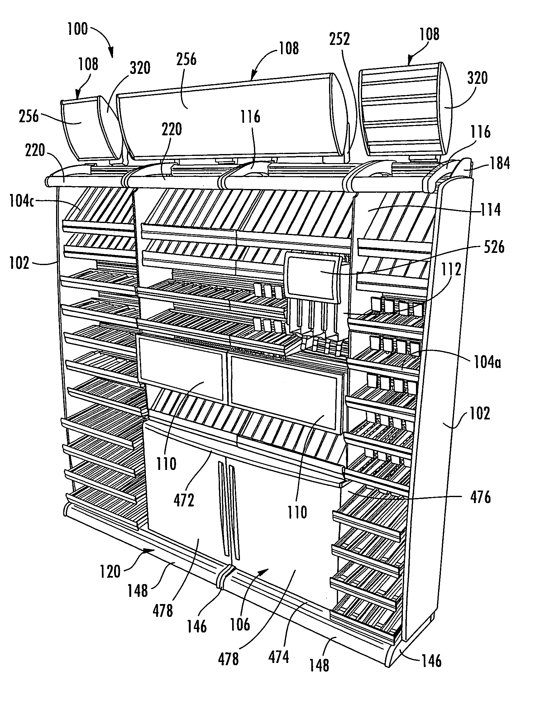
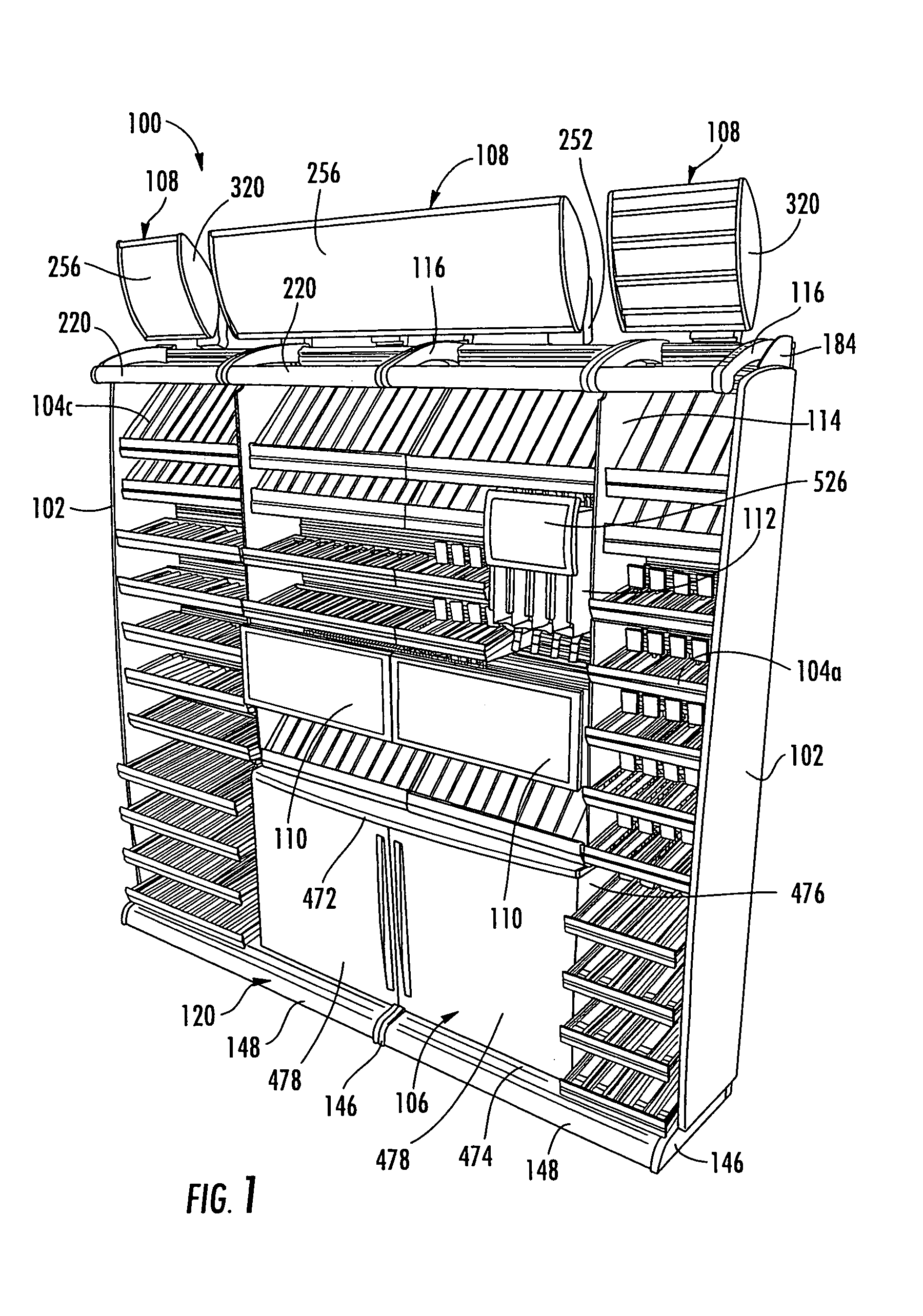
[0103]The present invention will now be described with reference to the accompanying drawings where the reference numerals in the following written description correspond to like-numbered elements in the several drawings. A display stand 100 according to one embodiment of the present invention is depicted in FIG. 1. Display stand 100 includes a pair of vertical end panels 102 positioned at the ends of stand 100, a plurality of shelves 104, a cabinet 106, a plurality of illuminated top signs 108, a plurality of interior signs or light boxes 526, and a gravity fed product dispenser 112. A pair of vertical divider panels 114 divide the shelves into a plurality of columns. One or more light brackets 116 may also be included along the top of display stand 100 to support the lights that help illuminate the product positioned on the shelves. While display stand 100 can be used to support any type of products, the illustrated embodiment is especially suited for supporting and displaying cig...


PUM


Abstract

A point of purchase display stand for displaying products includes shelving, lights, cabinets, signs, baskets, and other items that may be supported on a slot wall positioned in the back of the stand. The slot wall may be made up of horizontal slots that allow the aforementioned items to be positioned at a plurality of vertical locations and a virtually infinite number of horizontal locations. End panels and doors may also be added to the display stand for providing security to the contents of the display stand. The shelves may only require a small amount of rotation to be removed from the slot wall. The shelves may be oriented in a plurality of different angular orientations, and they may be optionally connected with adjacent shelves so that any sagging of a given shelf is transmitted to the adjacent shelves, thereby maintaining the shelves in horizontal alignment with each other.

Description

CROSS REFERENCE TO RELATED APPLICATIONS[0001]This application claims priority to U.S. provisional application Ser. No. 60 / 388,891 filed Jun. 14, 2002 and entitled MODULAR, ADJUSTABLE DISPLAY RACK. This disclosure of this provisional application is incorporated herein in its entirety by reference.BACKGROUND OF THE INVENTION[0002]This invention relates generally to display racks, and more particularly to adjustable display racks used to display products for sale in retail locations.[0003]Retail display racks are used to display a wide variety of different products that are offered for sale. In the past, these retail display racks have suffered from a number of disadvantages. For example, past retail displays have often been manufactured having a fixed size and fixed arrangement for displaying the products. These past displays have also been limited in the location, arrangement, and ease of re-arrangement of the advertising and signs that accompany the display and which help to sell th...

Claims


Application Information

Patent Timeline
Patent Type & Authority Patents(United States)
IPC IPC(8): A47B43/00A47F5/00A47F5/08
CPCA47F5/0807A47F5/0018
Inventor NOOK, THOMAS J.GAVIN, GREGORY D.JOHNSON, ROBERT J.ZANG, DATHAN G.
Owner ALTRIA GRP DISTRIBUTION
Why Eureka
Try Eureka