Cutting chain grinder and method of grinding

a chainsaw and cutting chain technology, applied in the direction of edge grinding machines, other manufacturing equipment/tools, manufacturing tools, etc., can solve the problem that the torsional spring b>50/b> is difficult to replace when

Inactive Publication Date: 2007-02-13
OREGON TOOL INC
View PDF11 Cites 11 Cited by
  • Summary
  • Abstract
  • Description
  • Claims
  • Application Information

AI Technical Summary

Problems solved by technology

Also, the torsional spring 50 is difficult to replace when it breaks because it requires disassembly of the grinder head 22 from the grinder base 26.

Method used


Image

  • Cutting chain grinder and method of grinding
  • Cutting chain grinder and method of grinding
  • Cutting chain grinder and method of grinding

Examples


Embodiment Construction

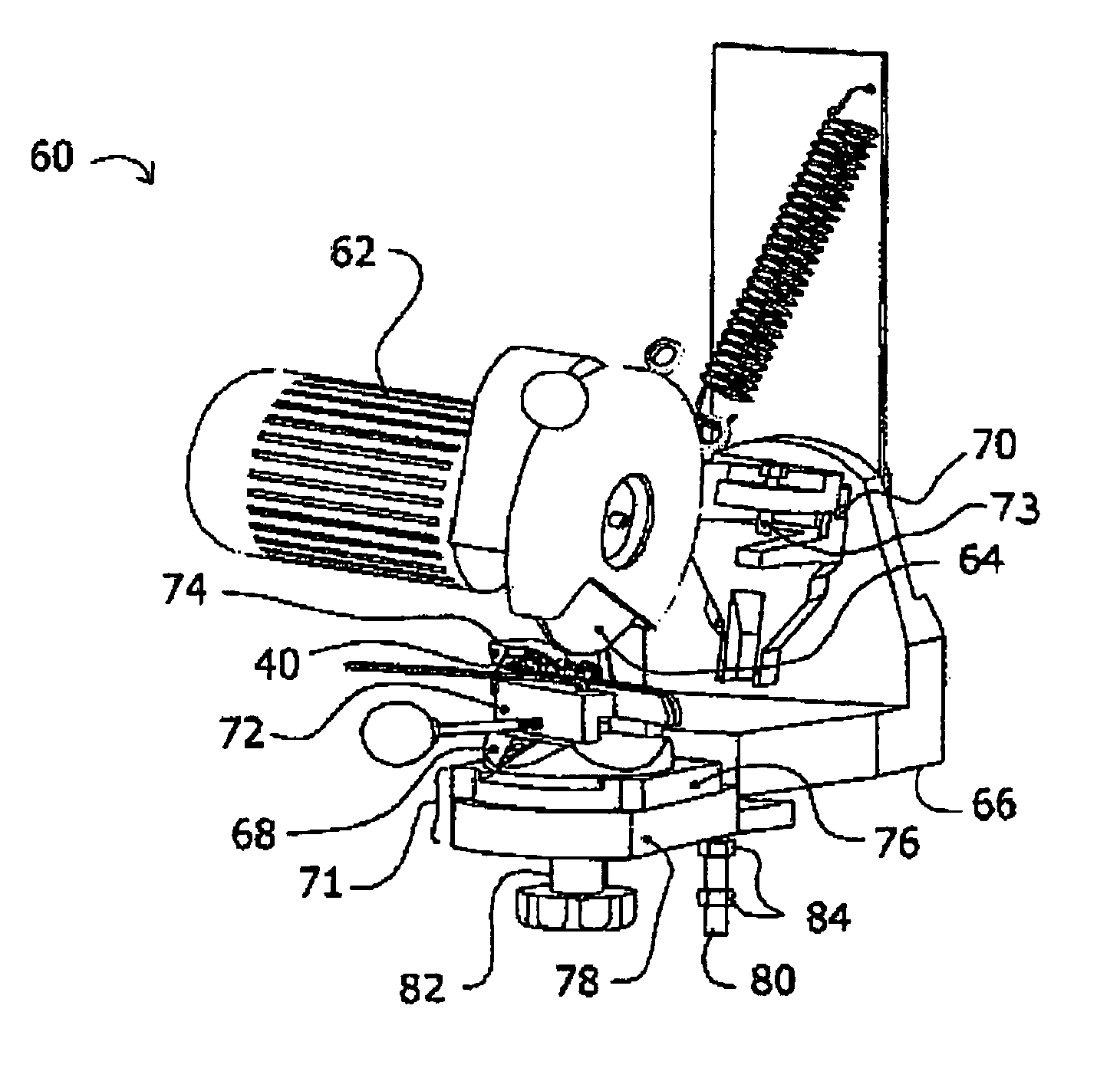
[0022]FIG. 3 is a perspective view of a cutting chain grinder 60 according to an embodiment of the invention. Grinding head 62 housing the grinding wheel 64 is mounted on the grinder base 66 at hinge 70. A self-centering chain vise assembly 68 is mounted on a front portion 71 of the grinder base 66. The chain vise assembly 68 includes self-centering vise 72 which holds chain 40 for grinding.

[0023]The self centering chain vise assembly 68, like current grinders, is rotationally adjustable about an axis of rotation that is substantially normal to a horizontal plane of the vise assembly 68. The self-centering chain vise assembly 68 is positioned and adapted to adjust both sides of the vise 72 such that the longitudinal centerline of the cutting chain 40 intersects the axis of rotation of the vise assembly 68. By always centering the cutting chain 40 on the axis of rotation of the vise assembly 68, the cutter stop 74 need not be readjusted after rotating the vise assembly 68 to grind an...


PUM

PropertyMeasurementUnit
vertical angleaaaaaaaaaa
top plate angleaaaaaaaaaa

Abstract

A cutting chain bench grinder includes a self-centering vise that centers the cutting chain on an axis of rotation of the vise base. By centering the cutting chain to intersect the vise base axis of rotation, consistent top plate lengths and hook angles can be ground into left and right-hand cutters on a cutting chain. The vise base may also be adjusted horizontally in and out from the grinder base to align the vise base axis of rotation with the axis of rotation of the grinding wheel. The vise base may also be adjusted vertically relative to the vise base to vertically compensate for grinding wheel wear and to control grinding depth. A light tension spring may be used to bias the grinding head in both grinding and dressing positions. A down angle positioner may also be provided that rotates the cutting chain in the vise around a longitudinal centerline of the cutting chain.

Description

TECHNICAL FIELD[0001]This disclosure relates to cutting chains for chainsaws and more particularly to the maintenance grinding of the cutters on the cutting chain.BACKGROUND OF THE DISCLOSURE[0002]To maintain their sharpness, cutters on cutting chains must be ground after periods of use and whenever the cutting chain encounters rocks, contaminated wood, or other anomalous material. The cutters are sharpened on the chain by placing the chain in a bench grinder 20.[0003]FIG. 2 shows a typical cutter 36 with reference numbers identifying critical features which will be described more fully below including top plate length 42 and top plate angle 34.[0004]A depiction of a common bench grinder 20 is shown in FIG. 1. The common bench winder 20 has three main components: the grinder head 22 containing the grinding wheel 24; the grinder base 26; and the vise 28. The grinder head 22 is attached to the grinder base 26 at a top back pivoting binge 30. The vertical angle of the grinding wheel 24...

Claims


Application Information

Patent Timeline
Patent Type & Authority Patents(United States)
IPC IPC(8): B24B3/00B23D63/16
CPCB23D63/16
Inventor HUNTINGTON, KENT L.HAILE, DANIEL
Owner OREGON TOOL INC
Why Eureka
Try Eureka