Eureka AIR delivers breakthrough ideas for toughest innovation challenges, trusted by R&D personnel around the world.

Drag plate structure of numerical control external cylindrical grinding machine

A cylindrical grinding machine, plate structure technology, applied in the direction of grinding machine parts, grinding drive devices, grinding/polishing equipment, etc. Oil mist, increase maintenance costs and other issues, to achieve the effect of simplifying the structure, improving waterproof performance and saving costs

Active Publication Date: 2012-11-28
浙江晟禧精密机械科技有限公司
View PDF6 Cites 7 Cited by
  • Summary
  • Abstract
  • Description
  • Claims
  • Application Information

AI Technical Summary

Problems solved by technology

Moreover, the waterproof plate on the front side of the carriage is directly under the grinding area, which cannot completely prevent the intrusion of grinding fluid or oil mist, which seriously affects the movement accuracy and service life of the lead screw
In addition, the feed mechanism in the prior art is composed of many parts, the structure is complex, the requirements for installation and maintenance accuracy are relatively high, and the maintenance cost is also virtually increased.

Method used


Image

  • Drag plate structure of numerical control external cylindrical grinding machine
  • Drag plate structure of numerical control external cylindrical grinding machine
  • Drag plate structure of numerical control external cylindrical grinding machine

Examples


Embodiment Construction

[0025] The present invention will be further described in detail below in conjunction with the accompanying drawings.

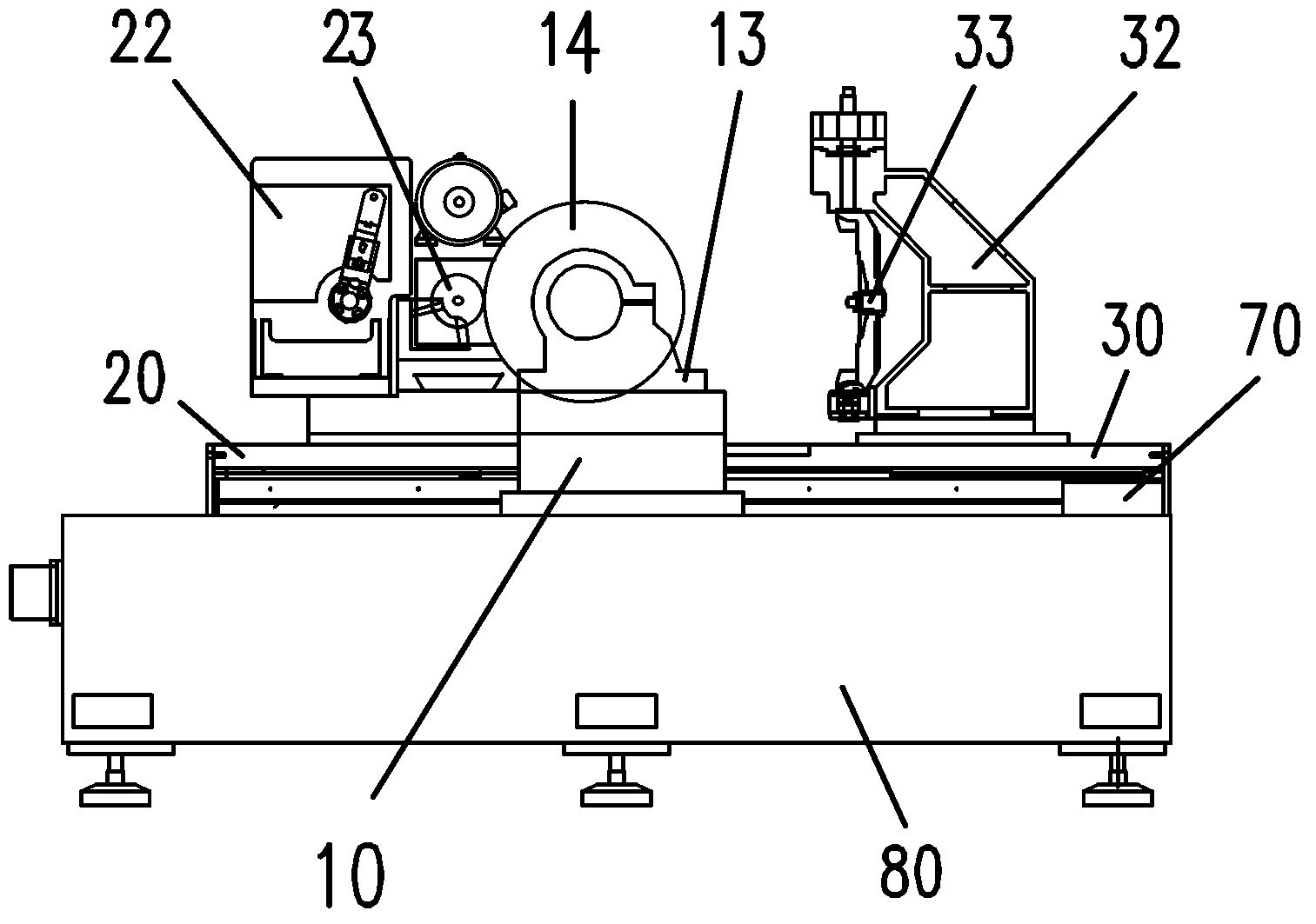
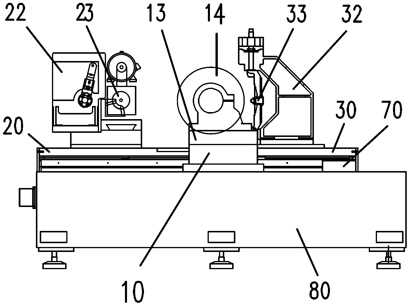
[0026] Such as Figure 1-2 As shown, the carriage structure of a CNC cylindrical grinding machine in the present invention includes a grinder base 10 , a workpiece carriage 20 and a dresser carriage 30 . The grinding wheel base 10 is fixed in the middle of the bed 80, and the workpiece moving mechanism 22 and the grinding wheel dresser 32 are separated on both sides; when the grinding machine is in the grinding state, the workpiece carriage 20 moves to the right, so that the surface of the workpiece 23 gradually approaches the grinding wheel 14, and accepts the grinding wheel. Cut; when the emery wheel surface damages, when needing reconditioning, the reconditioner carriage 30 moves to the left, allows reconditioning knife 33 near emery wheel 14, and emery wheel surface reconditioning is level off.

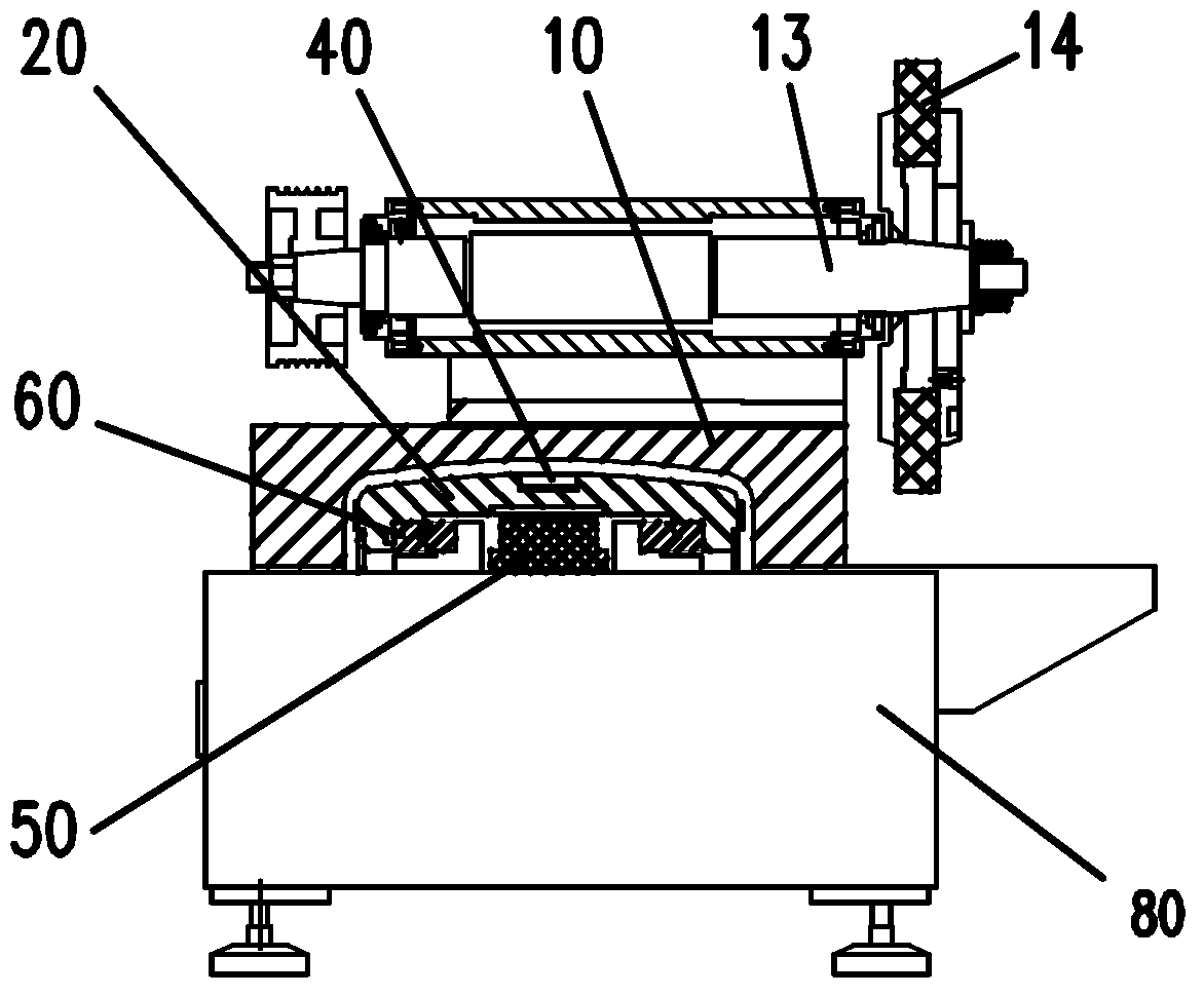
[0027] Such as image 3 As shown, the cross-sectional sha...


PUM


Abstract

The invention discloses a drag plate structure of a numerical control external cylindrical grinding machine. The drag plate structure comprises a grinding wheel machine seat, a workpiece drag plate and a repairer drag plate, wherein the grinding wheel machine seat adopts the structure of a bridge frame; supporting arms are arranged on the two sides of the bridge frame and connected with a machine body; a grinding wheel machine platform is arranged at the top of the bridge frame; the workpiece drag plate and the repairer drag plate are integrally connected by a connecting plate and mounted under the bridge frame of the grinding wheel machine seat; an arched arc surface is formed in the top of the drag plate; a through cavity is formed in the lower part of the drag plate; a linear motor and a rolling needle guide rail are arranged in the cavity; and a grating ruler is arranged on one side of the repairer drag plate and used for measuring the accurate positions of the workpiece drag plate and the repairer drag plate moving under the grinding wheel machine seat. The drag plate structure has the benefits as follows: the grinding machine seat adopts the structure of the bridge frame, so that the two upper drag plates can be integrally connected and are guaranteed to move synchronously; and the feeding action is driven by the same linear motor driver and positioned by the grating ruler, so that the feeding precision and the workpiece processing quality are improved.

Description

technical field [0001] The invention relates to a carriage structure of a grinder, in particular to a carriage structure of a numerically controlled cylindrical grinder. Background technique [0002] While grinding the workpiece, the grinder will also wear the grinding wheel on the grinding machine. In order to ensure the grinding accuracy of the workpiece, the shape of the grinding wheel must be trimmed. The cylindrical grinding machine in the prior art is usually centered on the grinder, and the workpiece movement mechanism and the dresser movement mechanism are distributed on both sides of the grinder, and each has its own bed carriage and drive mechanism. Although they slide on the same axis, the middle Disconnected by the grinder stand. Since the two carriages are respectively driven by servo motors and ball screws, the feeding accuracy depends entirely on the resolution of the two servo motors, the accuracy of the ball screw and the lead accuracy of the screw, any one...

Claims


Application Information

Patent Timeline
IPC IPC(8): B24B47/20
Inventor 朱江良曹强
Owner 浙江晟禧精密机械科技有限公司
Why Eureka
Eureka Blog
Learn More