
Dog lifting feeding mechanism of sewing machine and sewing machine

A technology of feeding mechanism and sewing machine, applied in the direction of feeding mechanism, sewing machine components, sewing equipment, etc., can solve the problems of broken needles, short service life of synchronous belts, inconvenient maintenance, etc., to ensure synchronization, low failure rate, Avoid offset effects

Active Publication Date: 2015-11-25
JACK SEWING MASCH CO LTD
View PDF12 Cites 25 Cited by
  • Summary
  • Abstract
  • Description
  • Claims
  • Application Information

AI Technical Summary

Problems solved by technology

But this sewing machine has the following defects in actual use: 1, because the main motor of the sewing machine directly drives the upper shaft, but the upper shaft first drives the upper and lower conveying shafts to rotate through the synchronous belt and the pulley, and the rotating up and down conveying shafts pass through The eccentric cam drives the upper and lower conveying arms and the cloth feeding table to reciprocate up and down, that is, the sewing machine jointly drives the cloth feeding mechanism through the rotation of the upper and lower conveying shafts and the swing of the horizontal conveying shaft, and the upper and lower conveying shafts are behind and the horizontal conveying shaft is in front. As a result, when the feed mechanism is adjusted to a small stitch distance, it is inevitable that the cloth feeding start time will be more advanced than when the stitch length is large, and the cloth feeding end time will be delayed more, and the total cloth feeding time will increase greatly. When the stitch distance is reduced to 3 stitches, the cloth feeding start time is advanced by 10° / 360°, and the cloth feeding end time is delayed by 15° / 360°; when the sewing machine is reduced from 5 stitches to 1 stitches, the cloth feeding starts The time is advanced by 20° / 360°, and the end time of cloth feeding is delayed by 25° / 360°; the advance time of cloth feeding start will cause poor thread take-up, and the delay of cloth feeding end time will cause needle breakage, which will affect the sewing quality
2. When the synchronous belt and pulley are used for transmission, the sewing machine is very noisy when running at low speed, and the service life of the synchronous belt is relatively short, and maintenance is inconvenient
3. The eccentric cam adopts bearings, so there is no lubrication and the service life is relatively short
4. The upper and lower conveying shafts are behind and the horizontal conveying shaft is in front. This structure is not conducive to material feeding

Method used


Image

  • Dog lifting feeding mechanism of sewing machine and sewing machine
  • Dog lifting feeding mechanism of sewing machine and sewing machine
  • Dog lifting feeding mechanism of sewing machine and sewing machine

Examples


Embodiment 1

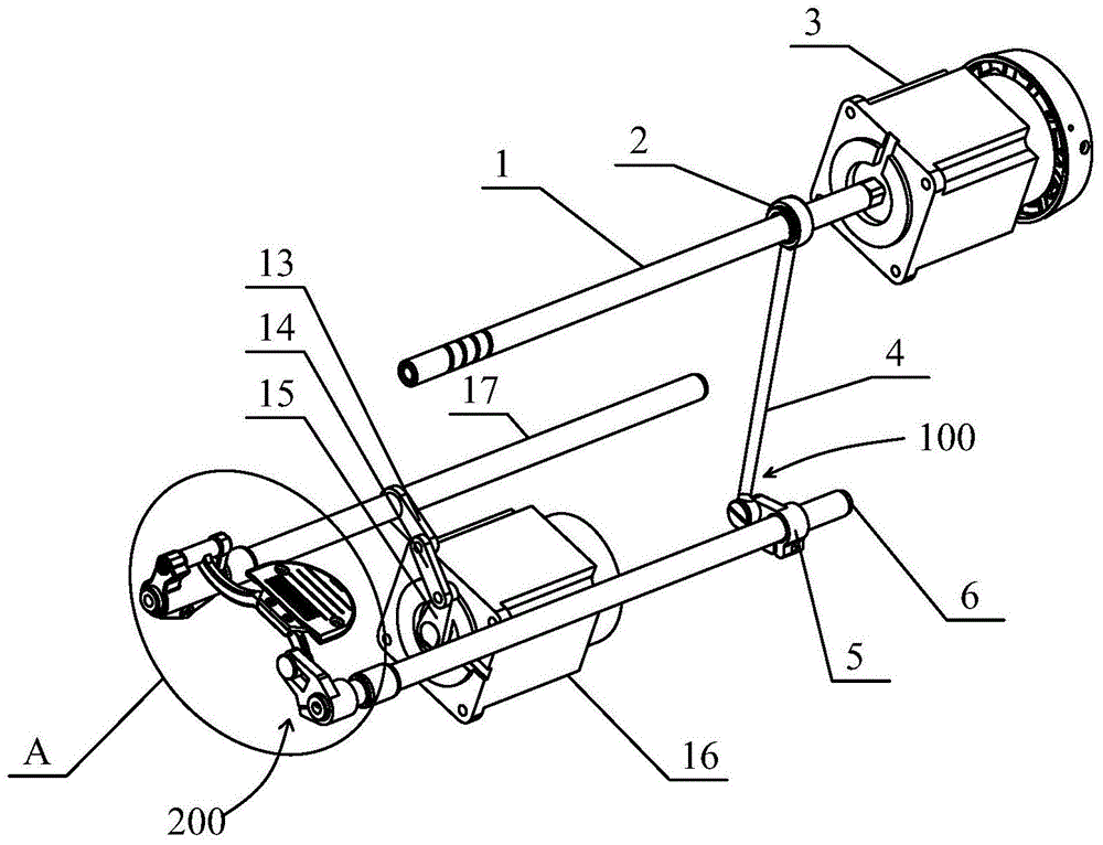
[0072] Embodiment one, as figure 1 As shown, the first transmission unit 100 includes a first eccentric cam 2 or an eccentric bearing fixed on the upper shaft 1, a tooth-lifting rear crank 5 fixed at one end on the tooth-lifting shaft 6, and a tooth-lifting connecting rod 4. The upper end of the tooth lifting connecting rod 4 is rotatably matched with the first eccentric cam 2 or the eccentric bearing, and the lower end of the tooth lifting connecting rod 4 is hinged with the other end of the tooth lifting rear crank 5 . In the present application, the first eccentric cam 2 is fixed on the upper shaft 1; the first eccentric cam 2 includes a first connection part connected with the upper shaft 2 and a second connection part connected with the teeth lifting link 4 , the first connecting part and the second connecting part are arranged eccentrically, so that the center of the upper end of the lifting link 4 does not coincide with the center of the upper shaft 1, so when the first...

Embodiment 2

[0073] Embodiment two, such as Figure 4 As shown, the first transmission unit 100 includes a first connecting rod 20, a second connecting rod 21 and a first slider 22, one end of the first connecting rod 20 is fixed on the upper shaft 1, and the second connecting rod 20 is fixed on the upper shaft 1. One end of the rod 21 is fixed on the lifting shaft 6, the first slider 22 is hinged to the other end of the first connecting rod 20, and is slidably sleeved on the second connecting rod 21, and the second connecting rod 21 Extend along the radial direction of the lifting tooth shaft 6. The upper shaft 1 drives the upper end of the first connecting rod 20 to rotate, so the lower end of the first connecting rod 20 swings back and forth with the axis of the upper shaft 1 as the center line, and is moved by the sliding of the first slider 22 on the second connecting rod 21. Drive the second connecting rod 21 to swing back and forth with the axis of the tooth lifting shaft 6 as the ...


PUM


Abstract

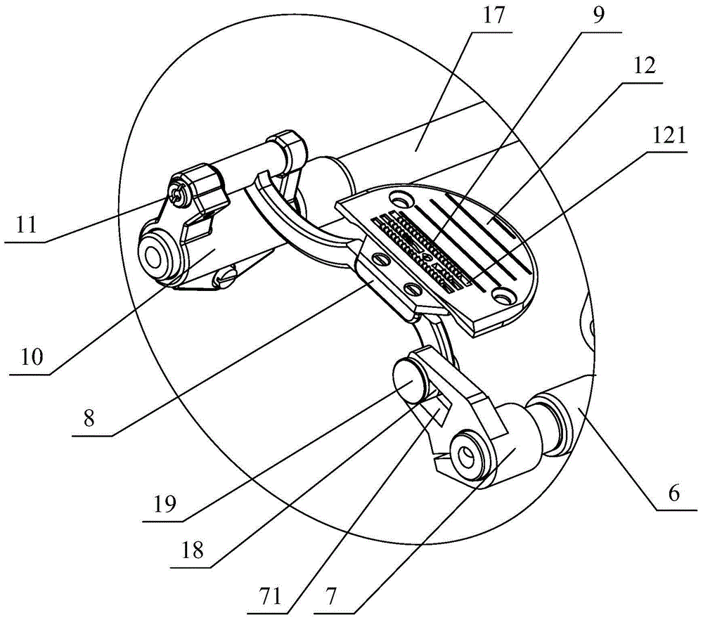
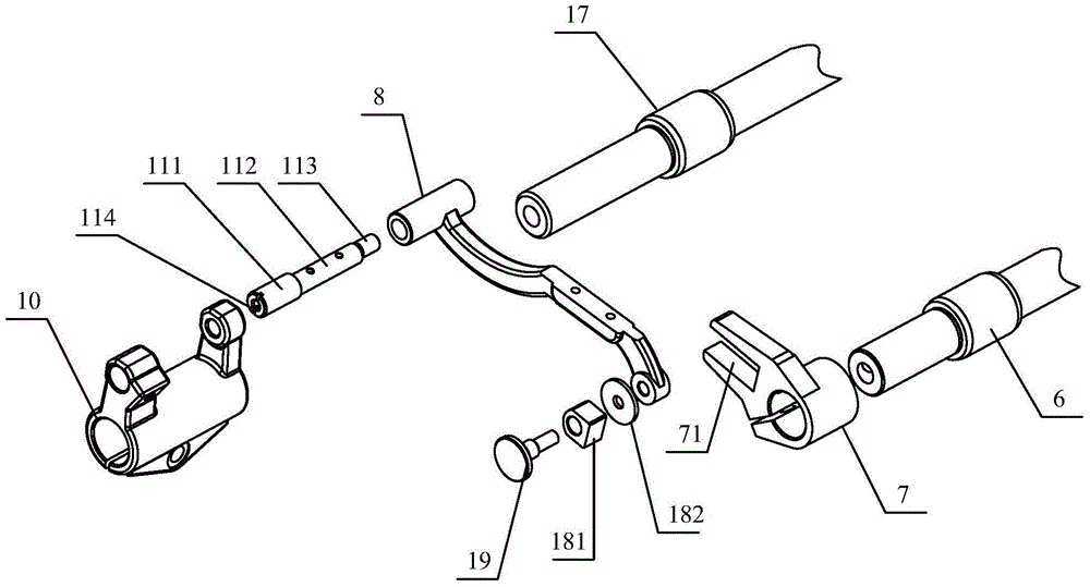
The invention provides a dog lifting feeding mechanism of a sewing machine. The mechanism comprises a first motor, a second motor, a dog rack and feed dogs fixed on the upper end surface of the dog rack, wherein the first motor is connected with the dog rack through a dog lifting mechanism; the second motor is connected with the dog rack through a cloth feeding mechanism; the dog lifting mechanism comprises an upper shaft and a dog lifting shaft which are arranged in parallel; the upper shaft is connected with the dog lifting shaft through a first transmission unit and drives the dog lifting shaft to swing back and forth with own axis as a center line; the dog lifting shaft is connected with the dog rack through a second transmission unit and drives the dog rack to reciprocate up and down. According to the dog lifting feeding mechanism of the sewing machine and the sewing machine, synchronism between rotation of the first motor and vertical movement of the dog rack can be guaranteed, deviation of a feeding time point is effectively avoided, and the noise is greatly reduced. According to the dog lifting feeding mechanism of the sewing machine and the sewing machine, synchronism between rotation of the first motor and vertical movement of the dog rack can be guaranteed, and deviation of a feeding time point is effectively avoided.

Description

technical field [0001] The invention relates to a garment sewing device, in particular to a sewing machine tooth lifting mechanism and a sewing machine. Background technique [0002] There are many kinds of sewing machines, including lockstitch sewing machines, overlock sewing machines, chain sewing machines, interlock sewing machines, etc. Among them, lockstitch sewing machines have the highest utilization rate. The sewing machine includes a stabbing mechanism, a thread hook mechanism, a thread take-up mechanism, a feeding mechanism, a winding mechanism, a pressing mechanism, etc., wherein the feeding mechanism mainly includes a tooth frame, a feeding tooth fixed on the upper end surface in the middle of the tooth frame, for A tooth lifting mechanism for driving the tooth frame to reciprocate up and down, a cloth feeding mechanism for driving the tooth frame to reciprocate back and forth, and a motor for driving the tooth lifting mechanism and the cloth feeding mechanism. ...

Claims


Application Information

Patent Timeline
Patent Type & Authority Applications(China)
IPC IPC(8): D05B27/02D05B27/10
Inventor 范晓鸿潘建国杨斌洪志敏林晓晓
Owner JACK SEWING MASCH CO LTD
Learn More