Integrated equipment of automatic robot welding system of standard knots

A robot welding and system integration technology, applied in welding equipment, auxiliary welding equipment, welding/cutting auxiliary equipment, etc., can solve the problems of high labor intensity of manual spot welding, unstable clamping of mechanical claws, poor welding quality, etc. Achieve the effect of improving welding quality and welding efficiency, avoiding frequent replacement of positioning blocks, and avoiding out-of-sync rotation

Active Publication Date: 2013-01-30
重庆立诚重工科技集团有限公司
View PDF7 Cites 23 Cited by
  • Summary
  • Abstract
  • Description
  • Claims
  • Application Information

AI Technical Summary

Problems solved by technology

Among them, the handling manipulator is equipped with a mechanical claw driven by a cylinder. The handling manipulator can realize the function of placing the workpiece and transferring the workpiece, while the spot welding positioning of the standard joint workpiece requires manual operation. The disadvantages are: First, the mechanical claw clamp The clamping is not stable enough, and accidents such as workpiece slipping are prone to occur, causing personal injury; secondly, manual spot welding is labor-intensive, poor welding quality, and low work efficiency
Its disadvantages are: firstly, it is necessary to weld the front and back of the horizontal film holder, then turn it over vertically for welding, and then turn it over as a whole for full welding. Due to the rotation inertia and impact force, or because the two sets of rack rotation mechanisms are out of sync, the coordinates of the standard joint weldment will be offset; again, the impact force of the rotation mechanism of the rack rotation mechanism will damage the positioning of the rack rotation mechanism stops, so frequent replacement of the positioning stops is required

Method used


Image

  • Integrated equipment of automatic robot welding system of standard knots
  • Integrated equipment of automatic robot welding system of standard knots
  • Integrated equipment of automatic robot welding system of standard knots

Examples


Embodiment

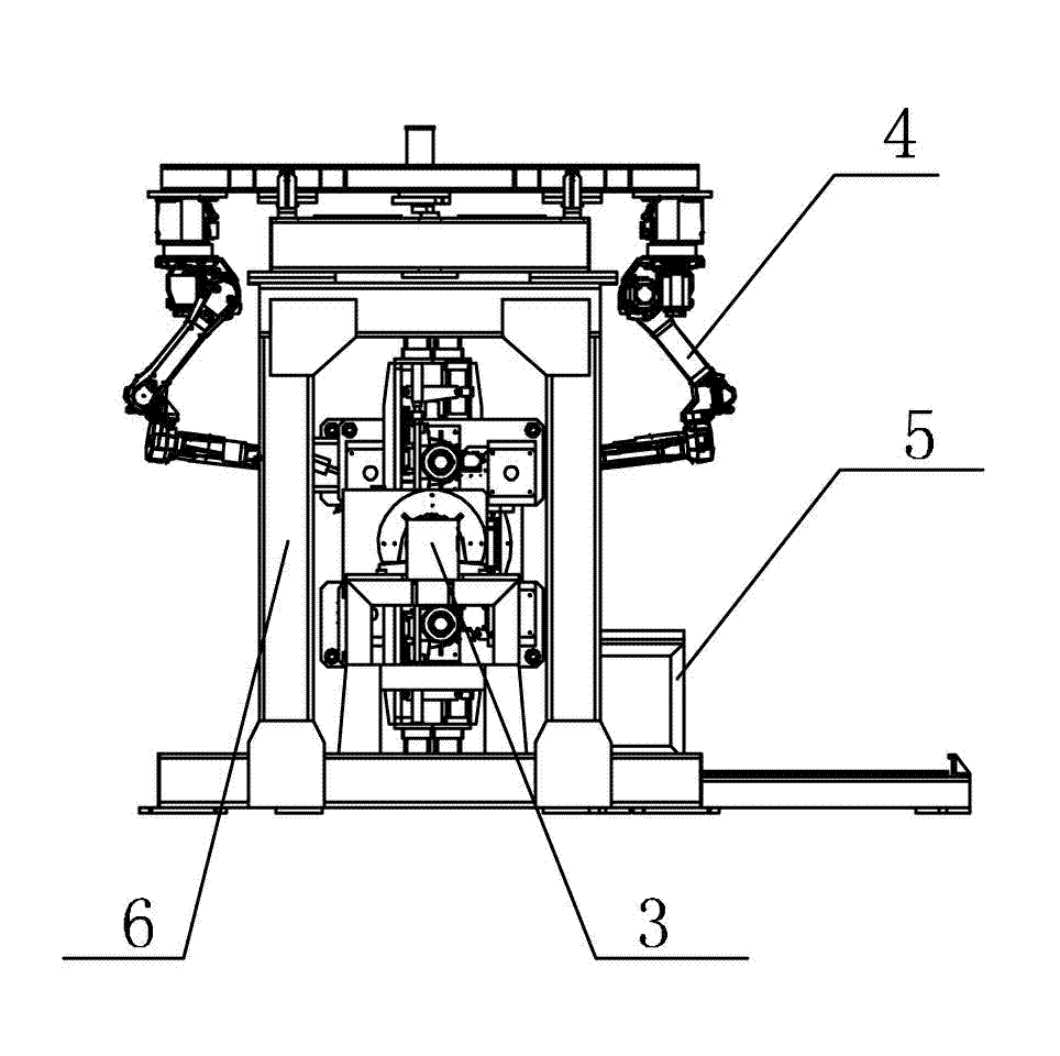
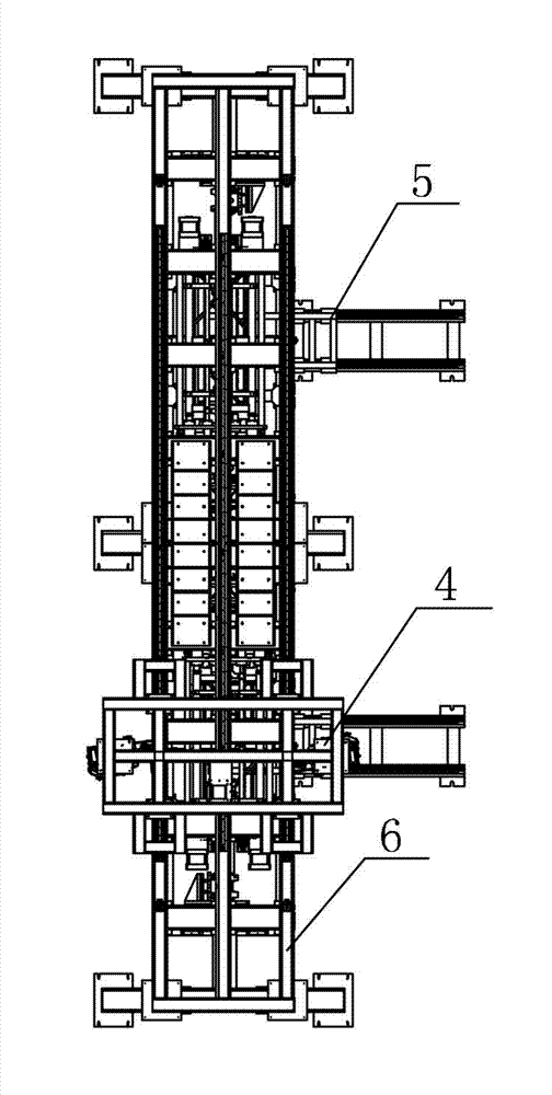
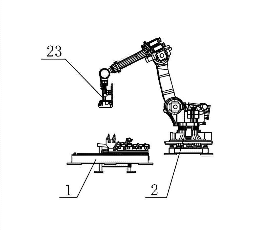
[0027] Example: such as figure 1 , figure 2 , image 3 , Figure 4 , Figure 5 , Figure 6 , Figure 7 and Figure 8 As shown, a standard section automatic robot welding system integration equipment is automatically controlled by the central controller of the standard section automatic welding system. The welding system integration equipment includes two feeding sliding table tooling 1 and one handling Manipulator 2, two standard joint displacement tooling 3, two welding manipulators 4 and two blanking mechanisms 5 also include a truss for installing welding manipulator 4, which is composed of a vertical support frame and a horizontal guide rail above the support frame.

[0028] Feeding slide tooling 1: Loading slide tooling 1 adopts a linear slide table, and feeding slide tooling 1 is equipped with a sliding mechanism 11 and a workpiece detection device. The workpiece detection device can be used to detect whether the workpiece is qualified, and the sliding mechanism ...


PUM


Abstract

The invention discloses integrated equipment of an automatic robot welding system of standard knots. The integrated equipment comprises a feeding sliding table tooling, a transporting manipulator, a standard knot deflection tooling, a welding manipulator and a discharging mechanism, wherein a three-dimensional coordinate detection device of the standard knot tooling is arranged on the standard knot deflection tooling; an electromagnetic clamp is arranged on the transporting manipulator; a welding gun guide track is arranged on the arm of the transporting manipulator; a welding gun sliding mechanism is connected with two sides of the welding gun guide track; a welding gun is fixed on the welding gun sliding mechanism; the rotary disc of the standard knot deflection tooling is integrally connected with a standard knot positioning bracket; the rotary disc is driven by a speed change motor; the welding manipulator is hung on a truss; and the standard knot deflection tooling is arranged below the truss. Compared with the traditional manual welding method, the consistency in welding quality, the welding efficiency and the safety reliability can all meet the requirements on the quality and the number in manufacturing modern high-tech products.

Description

technical field [0001] The invention relates to an automatic welding production line, in particular to a fully automatic welding system for standard joints of construction elevators in the construction industry. [0002] Background technique [0003] The welding automation level of automobile production line, construction machinery and other industries has been greatly improved due to the application of robots, but many large workpieces in the construction industry still use manual welding. Due to the complex structure of the standard joint, there are a series of characteristics such as a large number of welds, a variety of types, a large number of welding blind spots, and a wide spatial distribution. Therefore, in the past, simple fixtures and manual welding were generally used. The standard section mainly includes the main chord, flat frame bending parts, rack, rack connection block, diagonal rod and connection sleeve. The four main chords and two racks of the standard s...

Claims


Application Information

Patent Timeline
Patent Type & Authority Applications(China)
IPC IPC(8): B23K37/00B23K37/02B23K37/047
Inventor 吴泽元陈吉川陈世教刘传禄陈武
Owner 重庆立诚重工科技集团有限公司
Why Eureka
Try Eureka