Ergonomic rings for drum sticks, method of installation, and method of use

a technology of ergonomic rings and drum sticks, which is applied in the field of ergonomic rings for drum sticks, can solve the problems of prior art drum sticks, especially pronounced, inherent slippery nature of polished wood from which traditional drum sticks are manufactured, and achieve the effects of reducing the loss of drum sticks, and ensuring the accuracy of holding drum sticks

Inactive Publication Date: 2007-02-13
BROOKS ROBERT C
View PDF18 Cites 20 Cited by
  • Summary
  • Abstract
  • Description
  • Claims
  • Application Information

AI Technical Summary

Benefits of technology

[0017]It is another object of the present invention to provide ergonomic rings for drum sticks and methods which maintain the drummer's hands in the correct position on the drum stick. Design features allowing this object to be accomplished include at least one ergonomic ring frictionally engaged with a drum stick shaft positioned so as to guide the drummer's hand into position. A benefit associated with the accomplishment of this object is more accurate drum stick holding by the drummer.
[0018]It is still another object of this invention to provide ergonomic rings for drum sticks and methods which are adjustable for personal preference. Design features enabling the accomplishment of this object include at least one ergonomic ring frictionally engaged with a drum stick shaft. Advantages associated with the realization of this object include the ability to use the instant ergonomic rings with a wide variety of drummer hand sizes, and the cost savings associated with such standardization.
[0019]It is another object of the present invention to provide ergonomic rings for drum sticks and methods which help prevent a drum stick from slipping out of a drummer's hand. Design features allowing this object to be accomplished include at least one ergonomic ring frictionally engaged with a drum stick shaft. Benefits associated with the accomplishment of this object include decreased drum stick loss, associated enhanced performance quality, and reduced drummer fatigue.
[0020]It is another object of the present invention to provide ergonomic rings for drum sticks and methods which may be used with either the traditional or the match-grip style, and either left or right hand use. Design features allowing this object to be accomplished include at least one ergonomic ring frictionally engaged with a drum stick shaft. Benefits associated with the accomplishment of this object include increased installation versatility, and hence decreased cost.
[0021]It is still another object of this invention to provide ergonomic rings for drum sticks which may be installed on a new drum stick when the drum stick upon which the ergonomic ring was originally installed wears out. Design features enabling the accomplishment of this object include at least one ergonomic ring manufactured of resilient material, sized to frictionally and removably engage with a drum stick shaft. Advantages associated with the realization of this object include increased flexibility of use, and reduced cost.
[0022]It is yet another object of this invention to provide ergonomic rings for drum sticks which are inexpensive to manufacture. Design features allowing this object to be achieved include the use of components made of readily available materials. Benefits associated with reaching this objective include reduced cost, and hence increased availability.

Problems solved by technology

A number of problems exist with prior art drum sticks.
One problem especially pronounced in the case of beginners is holding shaft 4 in the correct location along its length.
Another problem is the inherent slippery nature of the polished wood from which traditional drum sticks are manufactured.
This problem becomes especially severe where the drummer is perspiring while playing.
Still another problem associated with traditional drum sticks is the force required to be exerted by the drummer merely to play the drums: because of the small diameter inherent in the design of traditional drum sticks, the moment generated by the drummer is small in direct proportion to the small drum stick diameter.
While this design helped prevent the drum stick from slipping out of the drummer's hand, the distance between the two ring series was fixed, and thus was not adjustable for the finger size of the individual drummer.
However, the distance between the two rings was approximately equal to the width of the drummer's hand, which is too great a distance for use with the instant method.
In addition, the position of the rings on the drum shaft was limited by the location of existing grooves and pre-drilled holes into which the rings were intended to fit.
Thus, the Simpson '194 rings were not infinitely adjustable along the length of the drum stick shaft, thus negatively affecting their adjustability to individual drummer preference.
Finally, the Simpson '194 rings were taught to be spiral constructions, rather than rings made of resilient material, thus increasing their complexity and consequently their cost.
While these patents taught frictional devices which helped prevent drum sticks from slipping out of the drummer's fingers, they did not provide locational guidance for the drummers grip.
In addition, no rings were taught which substantially add to the drum stick radius, thus preventing these designs from increasing the moment available to the drummer to help reduce drummer fatigue.
While the Blankenship '031 pistol grip design appeared to increase the grip of the drummer on the drum stick, the design rendered the stick difficult to grip using the traditional grip.
In addition, the grip was pre-sized, thus preventing adjustability for different hand sizes.
Similarly, although the Soderberg '043 post ball increased the moment arm available to the drummer when the post ball was pushed with the thumb, this design appears inappropriate for use in the traditional or match-grip style.
While these rings extended circumferentially around the bead, they did not aid in drummer grip nor drummer grip location on the drum stick.

Method used


Image

  • Ergonomic rings for drum sticks, method of installation, and method of use
  • Ergonomic rings for drum sticks, method of installation, and method of use
  • Ergonomic rings for drum sticks, method of installation, and method of use

Examples


Embodiment Construction

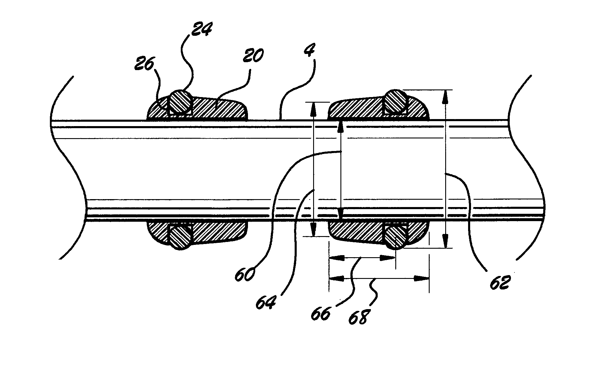
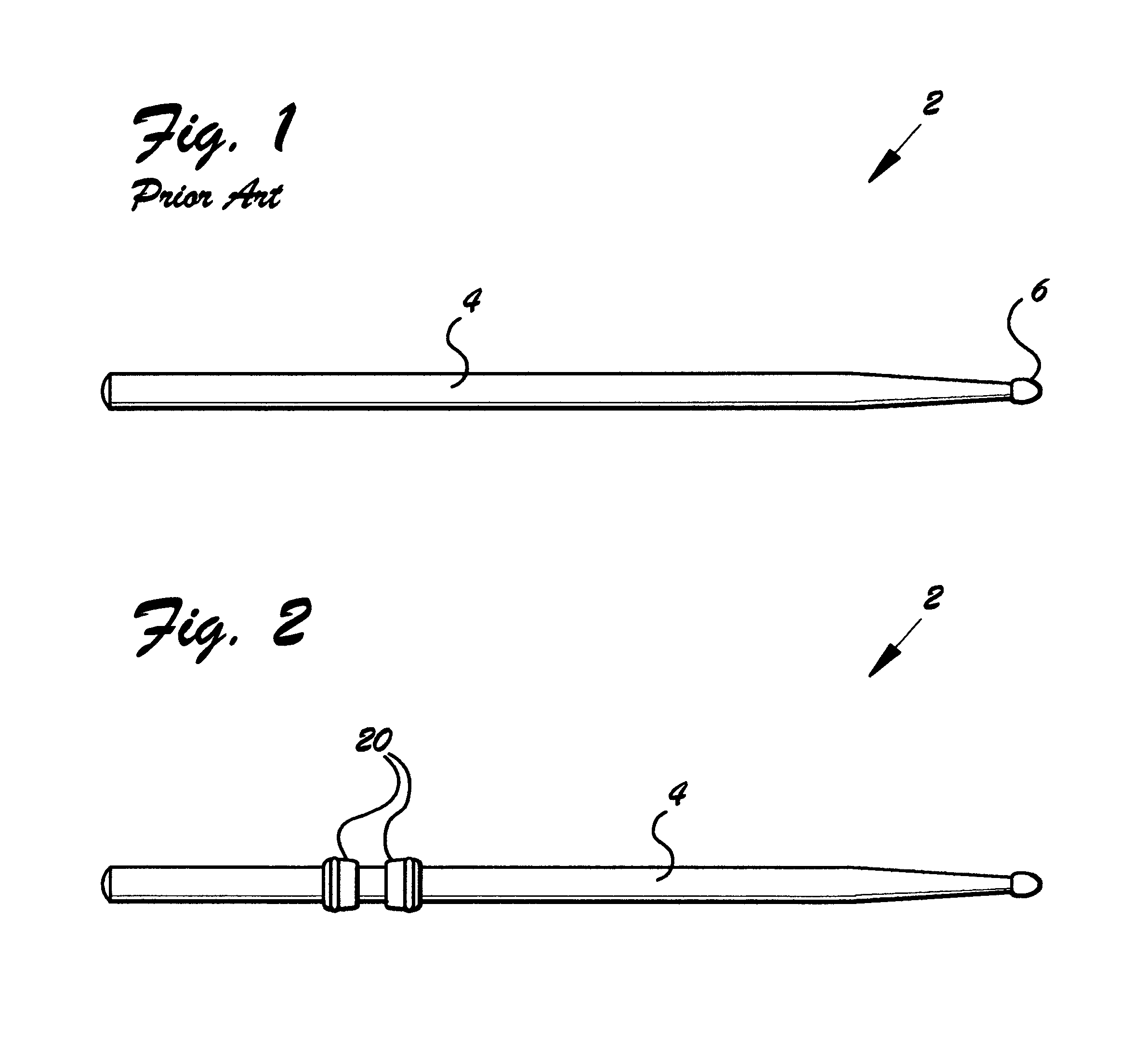
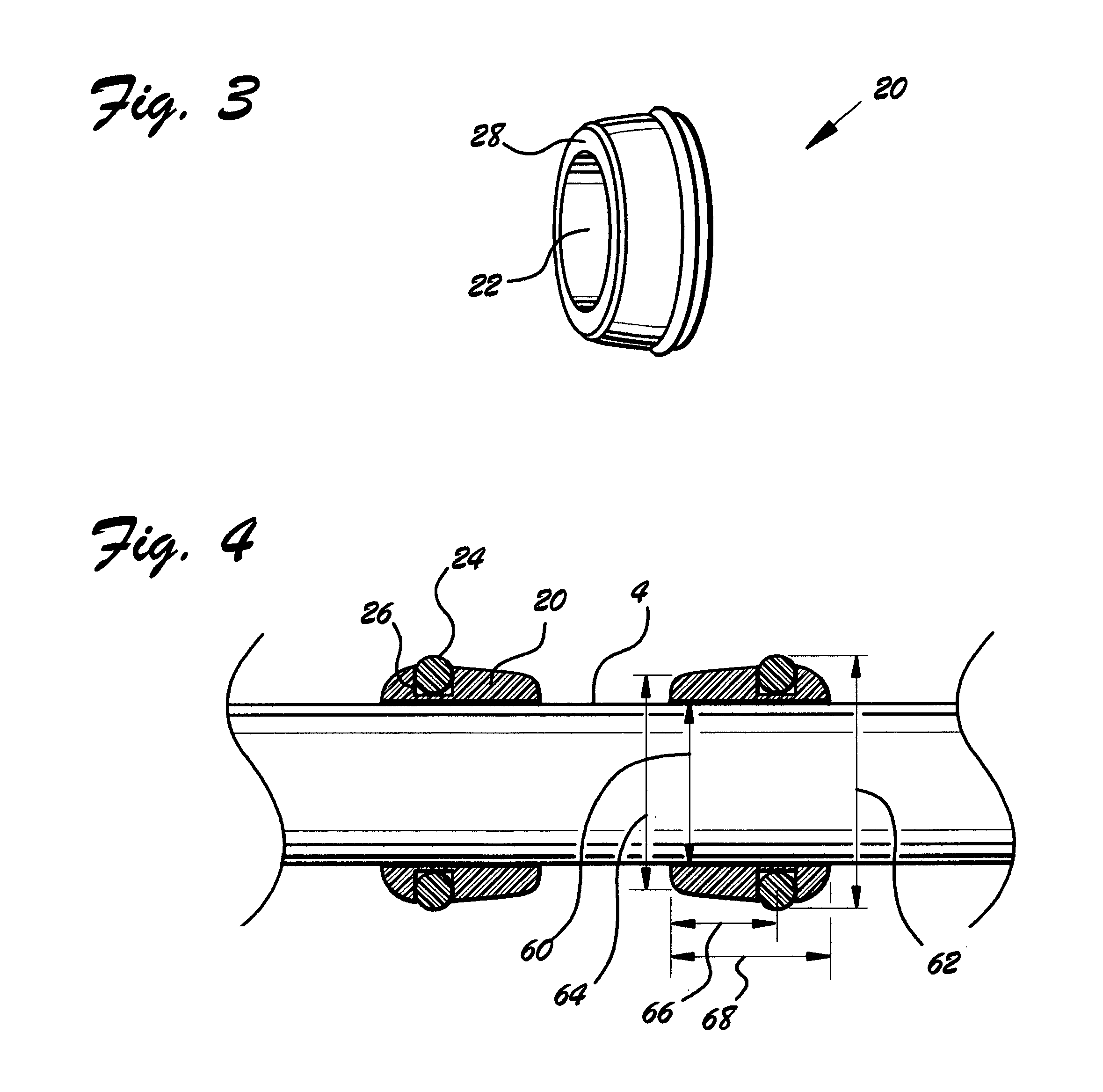
[0039]Referring now to FIG. 2, we observe a side isometric view of drum stick 2 with a pair of ergonomic rings 20 installed on its shaft 4. As may be observed in FIG. 3, a side quarter isometric view of ergonomic ring 20, ergonomic ring 20 comprises ergonomic ring bore 22. Ergonomic ring bore 22 is sized to frictionally admit shaft 4.

[0040]In addition, in the preferred embodiment, ergonomic ring 20 was manufactured of resilient material such as rubber. Thus, ergonomic ring 20 is capable of stretching to admit shaft 4. Once ergonomic ring 20 has been installed on shaft 20, its inherent resilience causes it to tightly grip shaft 4, thus maintaining its position in a desired location on shaft 4.

[0041]FIG. 4 is a side cross-sectional view of a pair of ergonomic rings 20 installed on a drum stick shaft 4. In the preferred embodiment, ergonomic ring 20 incorporated ergonomic ring groove 26 around its outer surface. Ergonomic ring groove 26 is sized to admit O-ring 24. O-ring 24 serves to ...


PUM


Abstract

Ergonomic rings for drum stick, method of installation, and method of use. A pair of resilient rings is installed on a drum stick spaced apart substantially by a distance equal to the width of a drummer's middle finger. The ergonomic rings have the effect of increasing drum stick radius, thereby substantially reducing the amount of force the drummer must expend to play the drum stick, reducing drummer fatigue, and increasing drummer speed. In addition, the rings aid in ensuring that the drummer's hand is disposed in the correct location along the length of the drum stick, and in preventing the drum stick from slipping out of the drummer's hand during play. Methods of installation and use are also disclosed.

Description

BACKGROUND OF THE INVENTION[0001]1. Field of the Invention[0002]This invention relates to drum sticks, and in particular to ergonomic rings for drum sticks, method of installation, and method of use.[0003]2. Background of the Invention[0004]Drums are one of the most important percussion instruments. These may be played by hand, or drum sticks may be used.[0005]FIG. 1 depicts a typical prior art drum stick 2 comprising shaft 4 terminating in bead 6. Drum stick 2 is employed to play a drum by holding its shaft 4, usually either in the traditional or match-grip style.[0006]A number of problems exist with prior art drum sticks. One problem especially pronounced in the case of beginners is holding shaft 4 in the correct location along its length. Another problem is the inherent slippery nature of the polished wood from which traditional drum sticks are manufactured. This problem becomes especially severe where the drummer is perspiring while playing. In this case, the drummer must expend...

Claims


Application Information

Patent Timeline
Patent Type & Authority Patents(United States)
IPC IPC(8): G10D13/02
CPCG10D13/003G10D13/12
Inventor BROOKS, ROBERT C.
Owner BROOKS ROBERT C
Why Eureka
Try Eureka