Magnetic recording disk drive with switchable rotational vibration cancellation

a magnetic recording disk and rotational vibration technology, applied in the direction of recording information storage, maintaining head carrier alignment, instruments, etc., can solve the problems of rv cancellation method degrading pes, disk drives experiencing rotational vibration and disturbance forces, and disturbances

Inactive Publication Date: 2007-02-13
WESTERN DIGITAL TECH INC
View PDF8 Cites 26 Cited by
  • Summary
  • Abstract
  • Description
  • Claims
  • Application Information

AI Technical Summary

Problems solved by technology

Disk drives experience rotational vibration and disturbance forces during normal operation.
These disturbances arise internally, such as from motion of the VCM actuator, as well as externally, such as from shocks to the frame supporting the disk drive or from the movement of other disk drives when the drives are mounted together in a disk array system.
However, the conventional RV cancellation method may degrade the PES when the RV sensor output includes large amounts of noise which are not related to the rotational vibration.
This problem becomes more critical as the track pitch becomes more narrow with the increasing data density of disk drives.
Examples of sensor-related noise include non-rotational vibrations detected by the sensor's cross-axis sensitivity, and / or spurious signals generated as a result of physical distortion of the sensor itself.
When the rotational vibration is detected by a RV sensor made up of a pair of linear accelerometers, the gain mismatch of the accelerometers also creates an undesirable compensation signal that degrades the PES.

Method used


Image

  • Magnetic recording disk drive with switchable rotational vibration cancellation
  • Magnetic recording disk drive with switchable rotational vibration cancellation
  • Magnetic recording disk drive with switchable rotational vibration cancellation

Examples


first embodiment

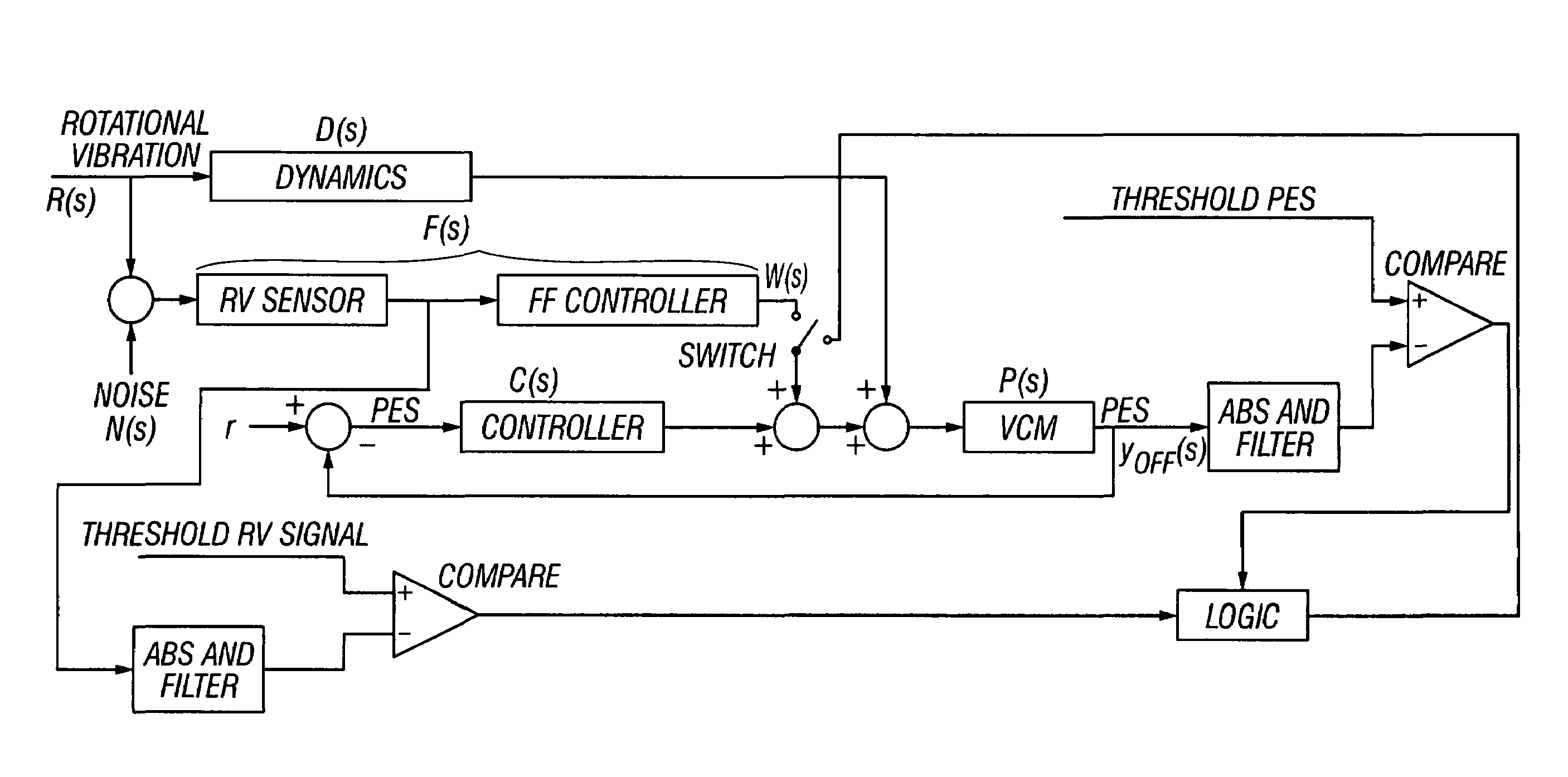
[0027]In the present invention the PES and the RV sensor output are used to determine when to enable and disable the RV feedforward compensation. FIG. 3 is control system loop for the invention. The compensation signal from the feedforward controller is “switchable”, meaning that the servo control processor can enable or disable it. The determination to enable or disable is made from a comparison of the PES with a threshold PES. The RV sensor signal is also compared with a threshold RV signal. The servo control processor uses the results of the two comparisons and certain logic to determine whether to enable or disable the RV sensor, i.e., to sum or not sum the feedforward compensation signal w(s) with the VCM control signal. The threshold PES and the threshold RV signal may be the known expected maximum values when the disk drive is subject to minimal disturbance, such as in the manufacturing test environment. In one possible logic, if the RV sensor is enabled and both the PES and ...

second embodiment

[0030]FIGS. 4A–4B are control system loops illustrating the invention wherein the threshold PES is an estimated off-track, with the RV sensor output being used to calculate the estimated off-track. If the RV compensation is enabled, as represented by the “switch” in FIG. 4A being closed, then the estimated off-track is an estimate of what the PES would be if the RV compensation was disabled. If the RV compensation is disabled, as represented by the “switch” in FIG. 4A being open, then the estimated off-track is an estimate of what the PES would be if the RV compensation was enabled. In either case, the RV sensor output, which affects the feedforward compensation signal w(s), is used to calculate the estimated off-track.

[0031]Referring first to FIG. 4A, when RV compensation is enabled, the measured or actual PES is given by the following equation.

[0032]yon⁡(s)=P⁡(s)1+P⁡(s)⁢C⁡(s)⁢(D⁡(s)⁢R⁡(s)+F⁡(s)⁢R⁡(s))Equation⁢⁢(2)

The estimated off-track when the RV compensation is disabled or off ...


PUM

PropertyMeasurementUnit
resonant frequencyaaaaaaaaaa

Abstract

A magnetic recording disk drive with rotational vibration (RV) cancellation uses the position error signal (PES) and the signal from a RV sensor to determine when to enable and disable RV cancellation. An RV feedforward compensation signal to be summed with the VCM control signal is “switchable”, meaning that it can be enabled or disabled by the disk drive servo control processor. The determination to enable or disable is made from a comparison of the PES with a threshold PES, which may be an estimate of the off-track position of the head calculated from the RV sensor signal. The estimated off-track is compared to the absolute value of the actual or measured PES. If the estimated off-track is smaller than the actual PES, then the state of the RV cancellation is switched, i.e., if it is enabled it is disabled and if it is disabled it is enabled.

Description

BACKGROUND OF THE INVENTION[0001]1. Field of the Invention[0002]This invention relates generally to magnetic recording disk drives, and more particularly to a disk drive that includes a system for canceling the effects of rotational vibration.[0003]2. Description of the Related Art[0004]Magnetic recording hard disk drives use an actuator, typically a rotary voice-coil-motor (VCM) actuator, for positioning the read / write heads on the data tracks of the recording disks. The disk drive has a servo control system that receives a position error signal (PES) from servo positioning information read by the heads from the data tracks and generates a VCM control signal to maintain the heads on track and move them to the desired track for reading and writing of data.[0005]Disk drives experience rotational vibration and disturbance forces during normal operation. These disturbances arise internally, such as from motion of the VCM actuator, as well as externally, such as from shocks to the frame...

Claims


Application Information

Patent Timeline
Patent Type & Authority Patents(United States)
IPC IPC(8): G11B5/596
CPCG11B5/5582
Inventor SEMBA, TETSUOWHITE, MATTHEW T.TZOU, KEVIN I.
Owner WESTERN DIGITAL TECH INC
Why Eureka
Try Eureka