

Image forming process and image forming apparatus
a technology of image forming apparatus and forming apparatus, which is applied in the direction of electrographic process apparatus, instruments, optics, etc., can solve the problems of limiting the compactness of the units surrounding the photoconductor, constant friction with these components, and gradual wear of the photoconductor surface, so as to suppress the uneven wear of the photoconductor over time, reduce the cost and small space, and eliminate uneven wear
- Summary
- Abstract
- Description
- Claims
- Application Information
AI Technical Summary
Benefits of technology
Problems solved by technology
Method used
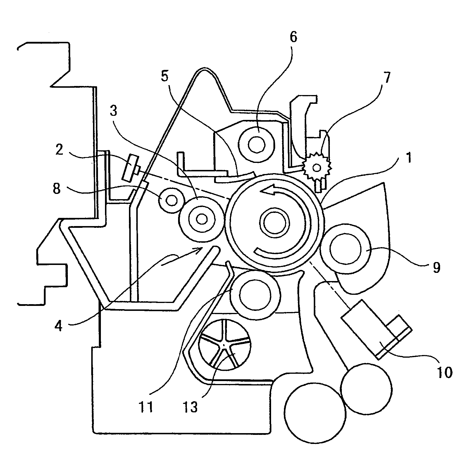
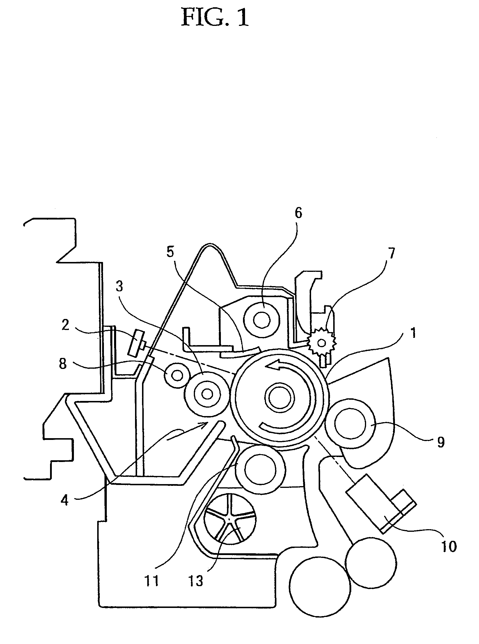
Image

Examples
example 1
(Toner Ingredients)
[0185]
Polyester resin89 parts by mass(Weight average molecular weight: 68,200, Tg:65.5° C.)Rice wax 5 parts by massCarbon black (Mitsubishi Chemicals: #44) 5 parts by massCharge controlling agent (Spiron Black TR-H: 1 part by massHodogaya Chemical Co., Ltd.)
[0186]The above ingredients were kneaded together using a 2-axis extruder at 120° C., crushed in an air crusher and classified to give a volume average particle diameter of 11.0 μm, and 2.2% by mass silica (R-972: Nippon Aerogel) was then mixed together using a Henschel mixer to obtain a toner.
[0187]The dynamic frictional coefficient of the obtained toner was 0.25, the wax peak ratio of the obtained toner was 0.153, the photoconductor surface frictional coefficient was 0.27, the toner circularity was 0.90, the volume average particle diameter was 11 μm and the cohesion degree was 3%. A carrier of magnetite particles of average particle diameter 50 μm coated with silicone resin (film thickness 0.5 μm), was mixed...
example 2
[0188]A sample was manufactured in an identical way to that of Example 1 except that 3 parts by mass of wax were used and the toner dynamic frictional coefficient was 0.43, the wax peak ratio of the obtained toner was 0.122, and an identical evaluation was performed. Table 1 shows the results.
example 3
[0191]A sample was manufactured in an identical way to that of Example 1 except that the photoconductor surface frictional coefficient was 0.5, the wax peak ratio of the obtained toner was 0.153, and an identical evaluation was performed. Table 1 shows the results.
PUM
 Abstract
Description
Claims
Application Information