Implantable cardiac stimulator wherein AV-delay adjustment is limited during dynamic atrial overdrive

Inactive Publication Date: 2007-02-13
ST JUDE MEDICAL
View PDF9 Cites 14 Cited by
  • Summary
  • Abstract
  • Description
  • Claims
  • Application Information

AI Technical Summary

Benefits of technology

[0012]An object of the present invention is to provide automatic

Problems solved by technology

While this is physiological during exercise and of benefit in DDD/VDD pacing at higher rates, the shortening is, as first understood by the inventor herein, less appropriate during periods of high stimulatio

Method used


Image

  • Implantable cardiac stimulator wherein AV-delay adjustment is limited during dynamic atrial overdrive
  • Implantable cardiac stimulator wherein AV-delay adjustment is limited during dynamic atrial overdrive
  • Implantable cardiac stimulator wherein AV-delay adjustment is limited during dynamic atrial overdrive

Examples


Example

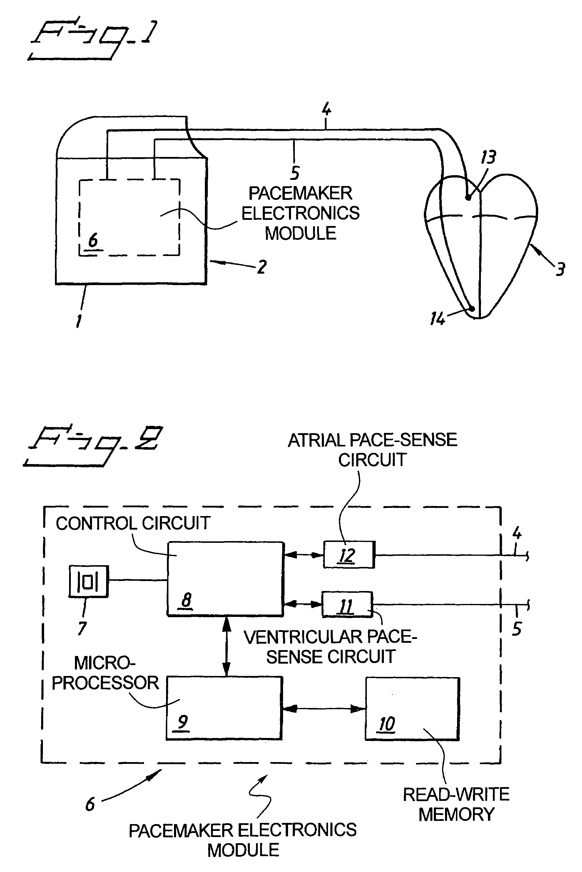
[0025]FIG. 1 shows a typical cardiac pacemaker 1 with a pacemaker electronics module 6 inside a hermetically sealed enclosure 2. The cardiac leads 4 and 5 with attached electrodes 13 and 14 conduct stimulation pulses to the patient's heart 3. Signals originating from P-waves and R-waves are picked up by electrodes 13 and 14 and conducted by the leads 4 and 5 to the pacemaker electronics module 6 which includes circuitry for detection of those signals.

[0026]FIG. 2 shows a typical design of a pacemaker electronics module 6. The electronics module 6 contains the following elements: micro-processor 9, read-write memory 10, control circuit 8, rate responsive sensor 7, atrial pace-sense circuit 12 and ventricular pace-sense circuit 11. The rate responsive sensor may be either of a physiological type such as a respiration minute volume sensor or of an activity kind such as an accelerometer for measurement of body movements. The microprocessor 9 supervises the operation of the control circu...


PUM


Abstract

A cardiac pacemaker has an algorithm for dynamic overdrive of a patient's atria in order to suppress atrial tachyarrhythmias. The device further has circuitry for adapting the AV-delay during dynamic overdrive of the atria to a value adapted to the patient's needs.

Description

BACKGROUND OF THE INVENTION[0001]1. Field of the Invention[0002]The present invention relates to an implantable cardiac stimulating device of the type having the capability to adapt the AV-delay depending on different operating conditions of the cardiac stimulating device.[0003]2. Description of the Prior Art[0004]Under healthy heart conditions an exercise-induced increase in heart rate is followed by a shortening of the heart's physiologic P-R interval.[0005]In pacemaker technology the term AV-delay is used for AV sequential pacing and the term PV-delay is used for sensed P-waves followed by ventricular stimulations synchronized to the sensed P-wave.[0006]Hence, among the approaches to provide physiological pacing in modern DDD pulse generators, an algorithm for stimulation rate-correlated shortening of the AV / PV delay is used. While this is physiological during exercise and of benefit in DDD / VDD pacing at higher rates, the shortening is, as first understood by the inventor herein,...

Claims


Application Information

Patent Timeline
IPC IPC(8): A61N1/368A61N1/362
CPCA61N1/3622A61N1/3682
Inventor SCHULLER, HANS
Owner ST JUDE MEDICAL
Why Eureka
Try Eureka