

Refrigeration device and controller for refrigeration device
- Summary
- Abstract
- Description
- Claims
- Application Information
AI Technical Summary
Benefits of technology
Problems solved by technology
Method used
Image

Examples
embodiment 1
[0019]Hereinafter, a configuration and operation of a refrigeration device according to the present invention will be described with reference to the embodiments shown in the drawings.
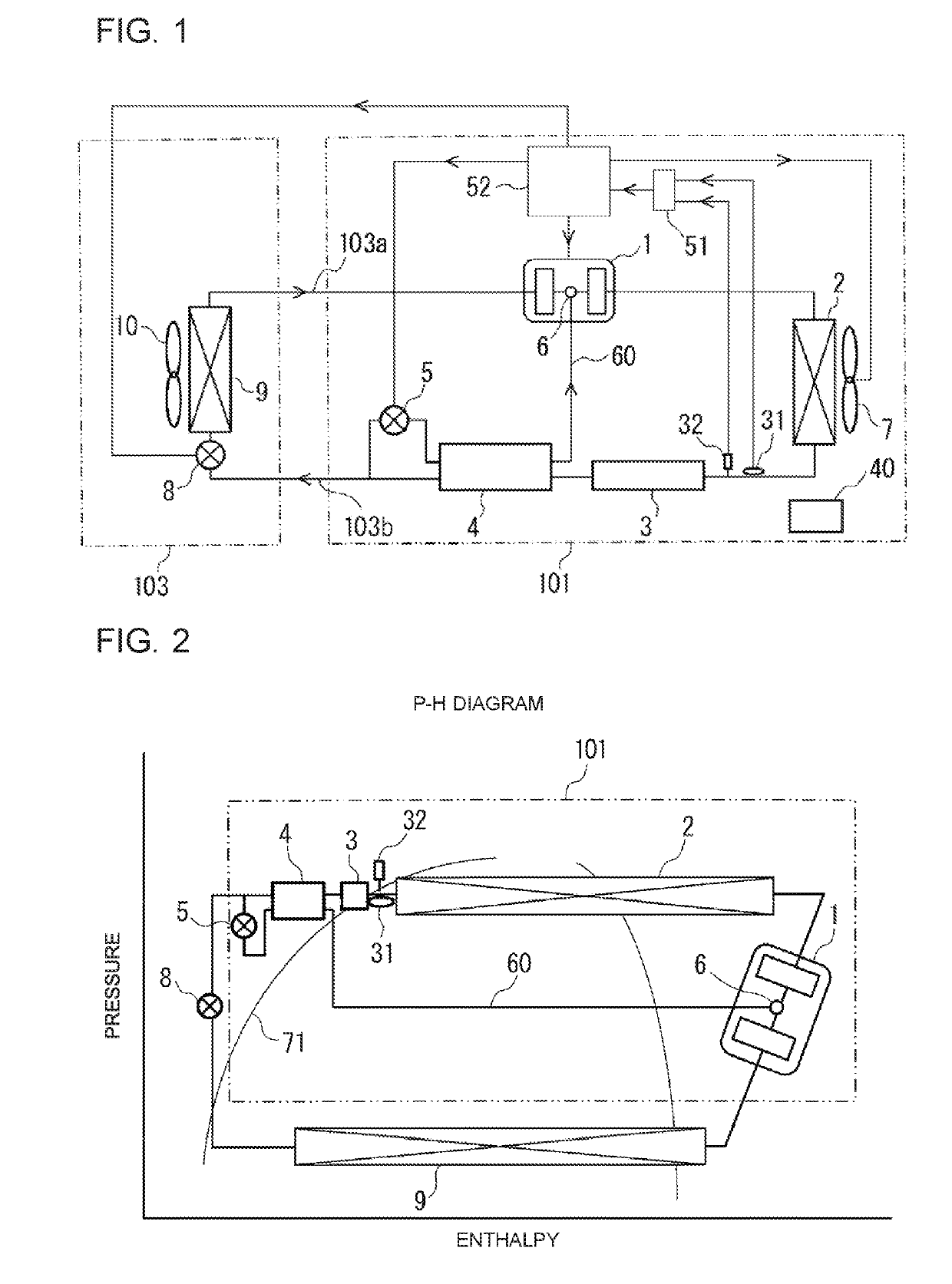
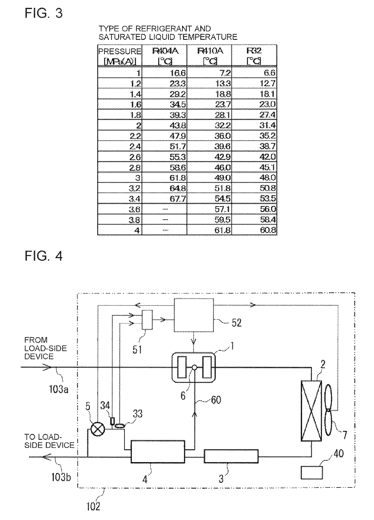
[0020]FIG. 1 is a schematic view showing a configuration example of a refrigerant circuit of a refrigeration device according to Embodiment 1 of the present invention. FIG. 2 is a p-h diagram showing an outline configuration of the refrigeration device according to Embodiment 1 of the present invention. FIG. 3 is a table showing data of a relationship between the types of refrigerants and saturated liquid temperatures in the refrigeration device according to Embodiment 1 of the present invention. Note that, relations between sizes of components in each of the drawings are different from those in actuality in some cases. Moreover, in each of the drawings, components assigned with the same reference signs are the same or corresponding components through all the sentences in the specification. Further, fo...
embodiment 2
[0050]Next, Embodiment 2 of the refrigeration device according to the present invention will be described with reference to FIG. 4.
[0051]FIG. 4 is a schematic view showing a configuration example of a refrigerant circuit of the refrigeration device according to Embodiment 2 of the present invention.
[0052]Note that, in Embodiment 2, description will be provided to focus on portions different from Embodiment 1, and portions same as those in Embodiment 1 are assigned with the same reference signs and description of the portions will be omitted.
[0053]A refrigeration device 102 according to Embodiment 2 is characterized in a configuration including an injection temperature sensor 33 serving as the temperature measurement unit and an injection pressure sensor 34 serving as the pressure measurement unit between the subcooling coil 4 and the injection expansion valve 5. Both injection temperature sensor 33 and injection pressure sensor 34 are, as an example, each configured with a thermisto...
embodiment 3
[0058]Next, Embodiment 3 of the refrigeration device according to the present invention will be described with reference to FIG. 5.
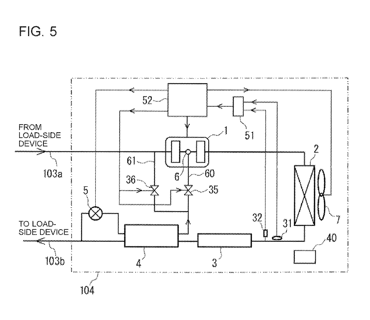
[0059]FIG. 5 is a schematic view showing a configuration example of a refrigerant circuit of a refrigeration device according to Embodiment 3 of the present invention. Note that, in Embodiment 3, description will be provided to focus on portions different from Embodiments 1 and 2, and portions same as those in Embodiment 1 are assigned with the same reference signs and description of the portions will be omitted.
[0060]In a refrigeration device 104 according to Embodiment 3, an injection bypass 61 branching from a point between the subcooling coil 4 and the compressor 1 for injection to the suction part (low-pressure part) of the compressor 1 is connected. Moreover, the injection circuit 60 is provided with an injection solenoid valve 35 and the injection bypass 61 is provided with an injection bypass solenoid valve 36. Opening and closing of the injectio...
PUM
 Abstract
Description
Claims
Application Information