Apparatus, method and computer program product for modelling causality in a flow system

a flow system and causality technology, applied in the field of apparatus, a computer program product and causality modelling in the flow system, can solve the problems of many systems and often very difficult to recognise, the level of the tank affecting the flow through the pump, and the flow through the tank will be too low

Inactive Publication Date: 2007-02-13
GOALART
View PDF4 Cites 31 Cited by
  • Summary
  • Abstract
  • Description
  • Claims
  • Application Information

AI Technical Summary

Problems solved by technology

This is due to the fact that the overall goal and functions in complex flow systems are many and often very hard to recognise using classical modelling methods.
For example it is obvious that a pump providing water to a closed tank affects the water level in the tank and that the level in the tank also affects the flow through the pump.
If the level in the tank is too high, the pump will not be able to transport more water to the tank since the tank is full, thus the flow through the tank will be too low.
A drawback with MFM of today is that it can not handle this latter case, since it is assumed in MFM that all connected components or parts of the flow system affect each other.
Another drawback with MFM is that it can not handle the case when the casual relationship between connected components for example changes over time.
However, this solution quickly becomes unmanageable, since it may be difficult to find the appropriate symbol to use in a specific system, and the modelling effort quickly becomes difficult.
However, Petersen does not provide a general solution of the problem and thus the causality between all functions, used to model the flow system, is not possible.
It is for example in the system disclosed by Petersen not possible to handle causality of a transport function or a barrier function, and Petersen does not propose a solution to the problem.
Further, with the disclosed system it is not possible to handle the causality dynamically, i.e. it is not possible to handle the case when the influence two connected functions affects each other with changes over time or due to other parameters controlling the operation states of the components of the flow system.
The system disclosed by Petersen is thus a static system and does not provide a general solution of how to model dynamical causalities of a flow system.

Method used


Image

  • Apparatus, method and computer program product for modelling causality in a flow system
  • Apparatus, method and computer program product for modelling causality in a flow system
  • Apparatus, method and computer program product for modelling causality in a flow system

Examples


example

A Multilevel Flow Model (MFM)

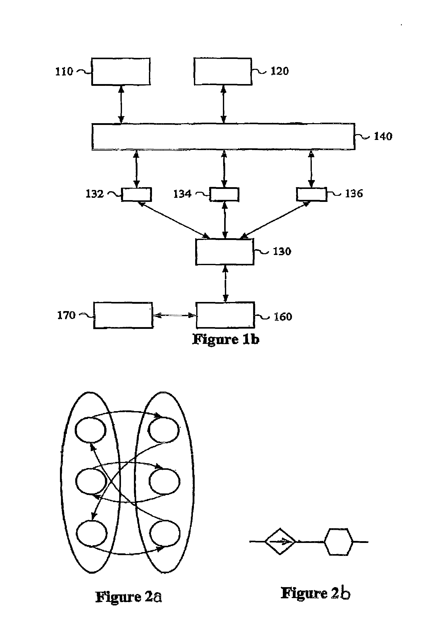
[0094]In MFM the added attribute to the causal relation indicates in which state a causal rule of the causal relation is active or not and can be shown graphically by adding a new modelling element indicating the direction in which the MFM functions affect each other. In the FIGS. 3b, 4b, 5b, 6b, 7b and 8b, examples of modelling elements indicating the direction in which the MFM functions affect each other is illustrated as an arrow between the functions. However, in the case of bidirectional effect no arrow is used.

[0095]The invention will now be exemplified by refers to FIGS. 2–10, wherein the shown states from the top of the state partitions and downwards are high, normal and low. However, it should be understood that the states are given as an example only.

[0096]In the exemplifying FIG. 2a, a bidirectional causal relation, having bidirectional causal rules, is shown, indicating that the MFM functions shown in FIG. 2b, i.e. the transport function and ...


PUM


Abstract

The present invention refers to an apparatus, a method and a computer program product for modelling causality in a flow system, and more specifically for modelling variable causality in the flow system. The apparatus 100 comprises a data storage means 110 configured to store model element data related to modelled components of the flow system, a causal rule storage means 120 configured to store a plurality of causal relations determining the causal relationships between model elements. The apparatus 100 comprises a state determination unit 130 arranged to receive a status signal from the flow system, identify the component related to the received status signal, identify a model element modelling the identified component and determine an operating state of the identified component. Further, the apparatus comprises a processing means 140 configured to activate or deactivate a causal relation related to the identified model element and dependent on the determined operating state.

Description

FIELD OF THE INVENTION[0001]The present invention refers to an apparatus, a method and a computer program product for modelling causality in a flow system, and more specifically for modelling variable causality in the flow system.BACKGROUND OF THE INVENTION[0002]Flow systems, such as industrial systems, can be described and modelled in several ways, and the models obtained are used for many different tasks, such as supervision, control, measurement validation, alarm analysis, fault diagnosis and sensor fault detection.[0003]Flow systems can for example be modelled by a model comprising qualitative descriptions of the system or by a so-called rule-based model, i.e., a model modelling the system using rules or logical statements describing how different components of the system interact with each other.[0004]Today more sophisticated models for modelling industrial system are available, for example so-called causal models. A causal model is a model, which models parts of the system and...

Claims


Application Information

Patent Timeline
Patent Type & Authority Patents(United States)
IPC IPC(8): G01F1/00G06F15/00G05B17/02G05B23/02
CPCG05B17/02
Inventor LARSSON, JAN ERICDAHLSTRAND, FREDRIKOHMAN, BENGT
Owner GOALART
Why Eureka
Try Eureka