
Spindle thermal distortion compensation method for precision horizontal machining center

A machining center and compensation method technology, applied in the direction of metal processing equipment, metal processing machinery parts, manufacturing tools, etc., can solve the problems of increasing cost and increasing system complexity, and achieve the effect of reducing thermal error

Inactive Publication Date: 2012-09-12
XI AN JIAOTONG UNIV +1
View PDF5 Cites 48 Cited by
  • Summary
  • Abstract
  • Description
  • Claims
  • Application Information

AI Technical Summary

Problems solved by technology

The above two methods can realize thermal error compensation and greatly reduce thermal error, but they need to add compensation hardware devices outside the system, and professional software programming is required, which not only increases the complexity of the system, but also increases the cost

Method used


Image

  • Spindle thermal distortion compensation method for precision horizontal machining center
  • Spindle thermal distortion compensation method for precision horizontal machining center
  • Spindle thermal distortion compensation method for precision horizontal machining center

Examples


Embodiment Construction

[0017] The present invention will be described in further detail below in conjunction with the accompanying drawings.

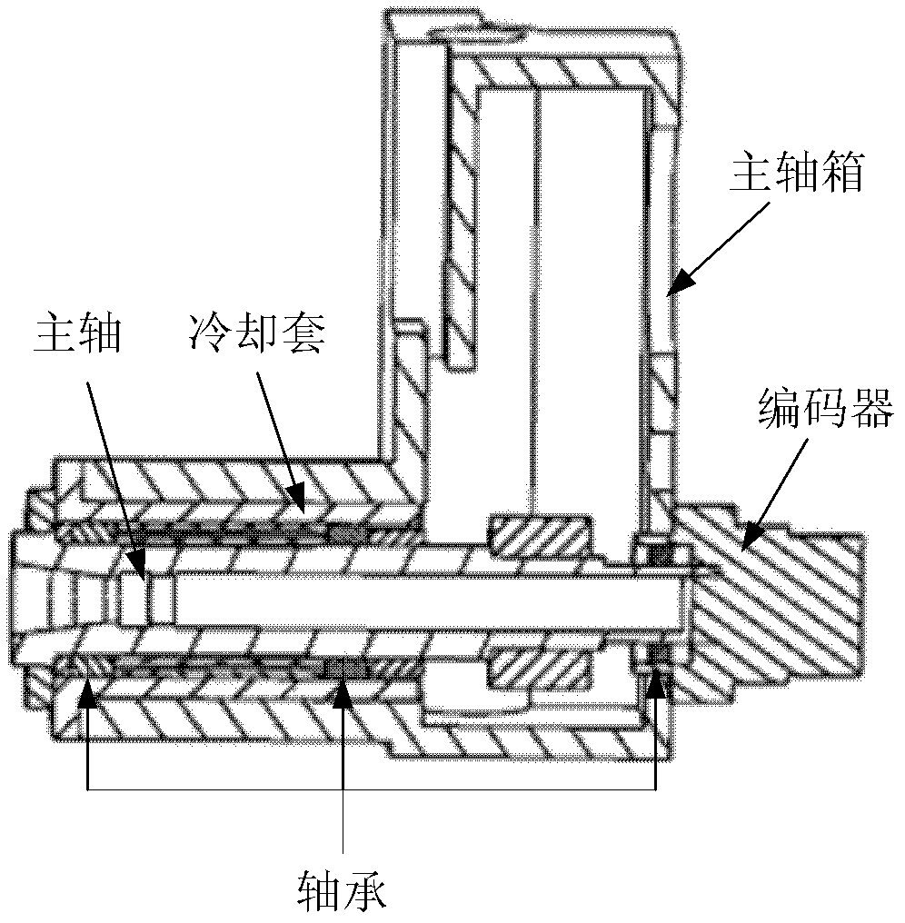
[0018] see figure 1 , 1. Finite element simulation of the temperature field and thermal deformation of the spindle system of the precision horizontal machining center

[0019] 1) The establishment of the finite element model and the application of boundary conditions: first, according to the structural characteristics of the machine tool spindle system, the spindle system of the precision horizontal machining center is simplified by Pro / E software, and the simplified solid model is imported into the ANSYS / Workbench analysis software for analysis. Mesh division: select different division methods according to the structural characteristics of different parts of the spindle system, such as selecting sweep division for regular structural cylinders and cubes, and selecting tetrahedron division or free division for components with complex structures. Combined with...


PUM


Abstract

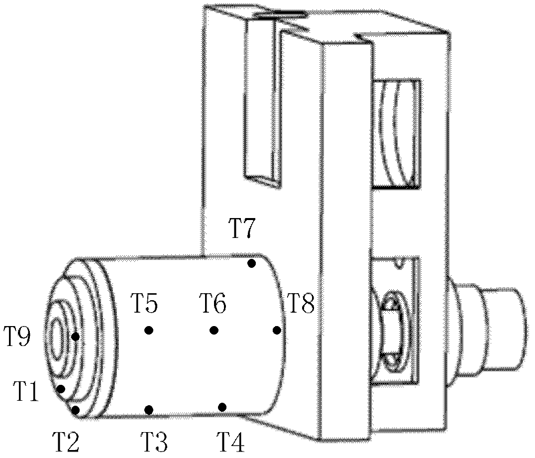
A spindle thermal distortion compensation method for a precision horizontal machining center comprises the steps as follows: a spindle model of a machine tool is simplified structurally; an ANSYS (finite element analysis software)-Workbench is utilized to perform mesh generation on a spindle entity model that is simplified, so as to obtain a spindle finite element model; and boundary conditions are calculated by combining with the practical spindle rotational speed, the environmental temperature, the coolant velocity, the flow rate, the inlet and outlet oil temperature and the like, and configuration is performed. Thermodynamics analysis and statics analysis are carried out in the ANSYS-Workbench to obtain more accurate spindle temperature field distribution and thermal deformation. Based on a finite element emulation result, the spindle temperatures in different positions and the spindle thermal deformations are analyzed at different rotational speeds by utilizing the Spearman rank correlation analysis, and spindle thermal key points are found out, so that references are provided to spindle thermal error tests and thermal error compensation. Finally, a thermal error compensation model is built up by utilizing a least squares method according to the key point temperature of the spindle and the thermal errors in the practical tests. Based on the thermal error compensation model, the spindle thermal error compensation is carried out by combining with thermal error compensation strategies of a numerical control system of the machine tool.

Description

technical field [0001] The invention belongs to the processing process of a precision horizontal machining center, and in particular relates to a method for compensating thermal error of a spindle of a precision horizontal machining center, including a temperature field of a spindle system and a thermal deformation finite element simulation calculation method, a method for selecting thermal key points, thermal error testing and construction modeling methods, and thermal error compensation implementation methods. Background technique [0002] As the key component of the machine tool, the performance of the spindle directly affects the machining accuracy, stability and application range of the machine tool. In recent years, high-speed spindles have become a development trend of spindles. However, the internal bearings of the spindle will generate a lot of heat under high-speed rotation, which will cause deformation of the spindle and affect the machining accuracy. At present,...

Claims


Application Information

Patent Timeline
Patent Type & Authority Applications(China)
IPC IPC(8): B23Q11/00B23Q17/00B23B19/02
Inventor 赵万华李旸位文明寸花英
Owner XI AN JIAOTONG UNIV
Learn More