A Prediction Method of Thermal Deformation of Feed Shaft

A prediction method and feed axis technology, applied in program control, instrumentation, computer control, etc., can solve the problems of unchangeable feed speed, low precision, and reduced compensation effect, so as to reduce design and prediction costs, and achieve high adaptability. and versatility, the effect of suppressing thermal errors

Active Publication Date: 2021-08-06
华中数控(温岭)研究院有限公司
View PDF6 Cites 0 Cited by
  • Summary
  • Abstract
  • Description
  • Claims
  • Application Information

AI Technical Summary

Problems solved by technology

This method requires the user to use the same processing G code as the modeling G code, and even the feed speed cannot be changed, which is poor in versatility; and due to the time-based compensation feature, it will vary with the process, processing speed and ambient temperature. The compensation effect will be greatly reduced, the accuracy is low, and sometimes even the compensation parameters need to be reset, which is very inconvenient to use
[0006] In view of the defects of the above two methods, the Chinese invention patent application CN106372337A proposed a thermal deformation prediction method in the heat engine stage based on the time-based thermal error compensation method, but because the large current difference and the environment when the gravity axis moves up and down are not considered The influence of temperature changes on heat dissipation factors, this method will produce larger errors when the gravity axis and ambient temperature change greatly

Method used


Image

  • A Prediction Method of Thermal Deformation of Feed Shaft
  • A Prediction Method of Thermal Deformation of Feed Shaft
  • A Prediction Method of Thermal Deformation of Feed Shaft

Examples


Embodiment Construction

[0031] In order to make the object, technical solution and advantages of the present invention clearer, the following will be further described in detail in conjunction with the embodiments. It should be understood that this embodiment is only an aspect of the application of the present invention, and is not intended to limit the present invention.

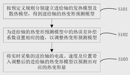
[0032] In some embodiments, such as figure 1 As shown, a feed shaft thermal deformation prediction method, which includes the following steps:

[0033] S101, respectively establish the heat generation model and heat dissipation model of the feed shaft according to the predefined rules, and obtain the thermal deformation prediction model of the feed shaft: ΔL i =Q 发 -Q 散 , where ΔL i is the thermal deformation of the screw, Q 发 is the calorific value of the feed shaft during motion, Q 散 is the heat dissipation of the feed shaft during motion.

[0034] The present invention is based on the principle of energy conservation, th...


PUM


Abstract

The invention discloses a method for predicting thermal deformation of a feed shaft, comprising the following steps: respectively establishing a heat generation model and a heat dissipation model of the feed shaft according to predefined rules, and obtaining a thermal deformation prediction model of the feed shaft: ΔL i =Q 发 -Q 散 ;Set the corresponding value for the thermal error compensation coefficient in the thermal deformation prediction model of the feed shaft to adjust the thermal deformation prediction model; bring the current, speed and position of the feed shaft collected in real time into the adjusted feed shaft Thermal deformation model to predict the corresponding thermal deformation. Based on the principle of energy conservation, the invention designs a thermal deformation prediction method of the feed shaft in view of the characteristics of energy consumption heating up and heat dissipation in the motion of the feed shaft. The invention overcomes the limitation that the non-gravity axis and thermal error compensation must work in a constant temperature environment, further reduces errors on the basis of suppressing thermal errors, reduces design and prediction costs, and has high adaptability and versatility .

Description

technical field [0001] The invention belongs to the technical field of error compensation of numerical control machine tools, and in particular relates to a method for predicting thermal deformation of a feed shaft. Background technique [0002] With the development of science and technology, many high-end products need to use CNC machine tools for precision machining. Taking aircraft as an example, my country has gradually become a major manufacturer of civil aviation aircraft parts. There is no doubt about the safety of aircraft, so the strength and dimensional accuracy of its structural components are very high. Many parts are integrally cast, with the characteristics of large volume and complex structure. However, the processing of a single piece generally takes a long time, so it is very susceptible to the influence of the ambient temperature and the thermal deformation of the machine tool structure. [0003] In order to achieve the ideal precision requirements, it is ...

Claims


Application Information

Patent Timeline
Patent Type & Authority Patents(China)
IPC IPC(8): G06F30/20G06F30/17G05B19/404G06F119/08
CPCG05B19/404G06F30/17G06F30/20G06F2119/08
Inventor 朱志红王旭杨祥尹乐胡洁周丹
Owner 华中数控(温岭)研究院有限公司
Why Eureka
Try Eureka