
Determination method of lead screw preload based on thermal error and temperature rise weighting

A preload, thermal error technology, applied in metal processing equipment, metal processing mechanical parts, electrical program control, etc., can solve the problem of shortening the service life, without considering the influence of the lead screw preload thermal error bearing temperature rise, acceleration Bearing wear and other issues

Active Publication Date: 2021-05-11
DALIAN UNIV OF TECH
View PDF3 Cites 0 Cited by
  • Summary
  • Abstract
  • Description
  • Claims
  • Application Information

AI Technical Summary

Problems solved by technology

[0004] The current method of reducing the thermal error of the feed shaft through the pre-tightening method of the screw has the following shortcomings: the pre-tightening amount of the screw is generally determined based on experience and mainly considers the suppression effect on the thermal error, and it is difficult to achieve the optimal effect in this way
If the pretightening amount of the screw is too small, the thermal error suppression effect is not enough; if the pretightening amount of the screw is too large, although the thermal error suppression effect is better, it will cause the temperature rise of the front and rear bearings of the screw to be too large, thereby Accelerate bearing wear and shorten service life
In the patent "A Method for Experimental Optimization of Ball Screw Preload of CNC Machine Tool Feed System" (Application No.: 201610285987.5), although the optimization of screw preload based on the positioning accuracy and dynamic characteristics of the feed axis is proposed method, but does not consider the influence of the screw preload on the thermal error and the temperature rise of the front and rear bearings, so the optimal screw preload obtained by this method cannot meet the common requirements for thermal error suppression and temperature rise control

Method used


Image

  • Determination method of lead screw preload based on thermal error and temperature rise weighting
  • Determination method of lead screw preload based on thermal error and temperature rise weighting
  • Determination method of lead screw preload based on thermal error and temperature rise weighting

Examples


Embodiment Construction

[0043] In order to make the purpose, technical solution and advantages of the present invention clearer, the present invention will be described in detail below in conjunction with the accompanying drawings.

[0044] Taking the X-axis of a certain type of vertical machining center as an example, the embodiment of the present invention will be described in detail. The X-axis stroke of the machining center is 0~-500mm, and the maximum feed speed is 32000mm / min.

[0045] The first step, the thermal behavior test of the feed shaft under typical working conditions

[0046]The first temperature sensor 3 is arranged on the front bearing 2 of the feed system, the second temperature sensor 7 is arranged on the nut 6, the third temperature sensor 10 is arranged on the rear bearing 11 of the feed system, and the fourth temperature sensor 9 is arranged On the bed 8 near the leading screw.

[0047] The machining center under test is for the consumer electronics industry, and the typical ...


PUM


Abstract

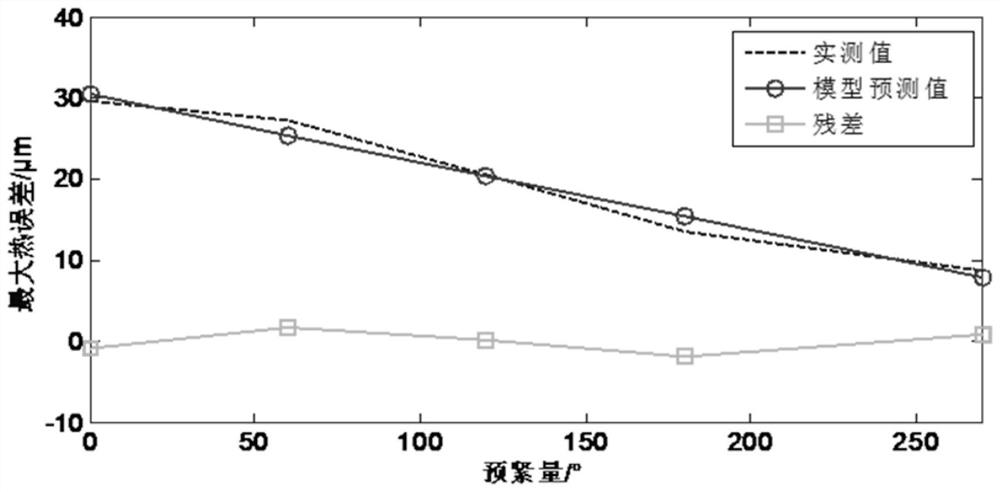
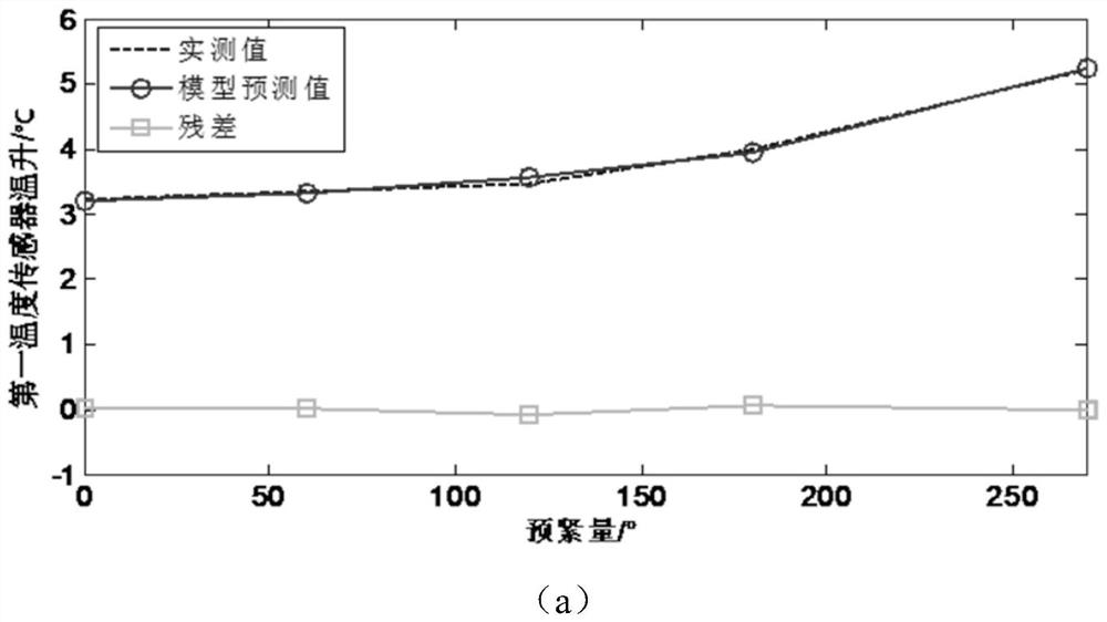
The invention provides a method for determining the pretightening amount of a lead screw based on thermal error and temperature rise weighting, and belongs to the field of numerical control machine tool assembly. First, under different preload states of the lead screw, the thermal behavior test of the feed shaft under typical working conditions is carried out to obtain the maximum thermal error of the lead screw under various preload states and the temperature rise of key temperature measuring points; then, establish The mathematical model of the screw preload, the maximum thermal error and the temperature rise of key temperature measuring points; finally, the weighted function of the maximum thermal error and the temperature rise of each temperature measuring point is optimized as the objective function, and the optimal prediction of the screw is obtained. Tight amount. This method comprehensively considers the thermal error of the feed shaft and the temperature rise of key points to determine the optimal preload of the screw, which solves the problem that the current experience-based screw preload method is difficult to achieve the optimal effect, and can improve the machining accuracy of the machine tool And precision stability, and ensure the service life of moving parts such as bearings.

Description

technical field [0001] The invention belongs to the technical field of numerical control machine tool assembly, and specifically relates to a method for determining the pretightening amount of a lead screw based on thermal error and temperature rise weighting. Background technique [0002] During the operation of the feed shaft, the friction between the nut and the lead screw will generate a lot of heat, and the heat transfer to the lead screw will cause the lead screw to thermally elongate. If the feed axis adopts a semi-closed-loop control method, the thermal elongation of the screw will cause a change in the positioning accuracy of the axis, and this change is the thermal error of the feed axis. This thermal error will eventually affect the machining accuracy of the workpiece and the accuracy consistency of batch processing. [0003] In order to reduce the thermal error of the semi-closed-loop feed shaft, the common method is to pre-tighten the screw, that is, to apply a...

Claims


Application Information

Patent Timeline
IPC IPC(8): G06F30/17B23Q5/40G06F119/08
CPCB23Q5/40G05B19/18
Inventor 刘阔王永青刘海波沈明瑞牛蒙蒙班仔优
Owner DALIAN UNIV OF TECH
Learn More