Eureka AIR delivers breakthrough ideas for toughest innovation challenges, trusted by R&D personnel around the world.

A 12kv switchgear structure with controllable temperature rise

A switchgear and temperature rise technology, applied in the field of 12kv switchgear structure with controllable temperature rise, can solve the problems of easy overheating, aggravated overheating, endangering the safety and service life of electrical equipment, etc., and achieves convenient cleaning and replacement, high efficiency The effect of controlling temperature rise

Active Publication Date: 2020-11-24
ZHEJIANG DISIWEI ELECTRIC
View PDF4 Cites 0 Cited by
  • Summary
  • Abstract
  • Description
  • Claims
  • Application Information

AI Technical Summary

Problems solved by technology

[0002] The switchgear, especially the 12kV switchgear, is prone to overheating due to various factors, and the internal overheating of the 12kV switchgear has become a common problem in the use of the switchgear. Due to the airtightness of the 12KV switchgear, some heavy load In some areas, there is often the problem of excessive temperature rise of 12KV switchgear
[0003] The temperature rise of the switchgear exceeds the standard, which directly affects the safe and stable operation of the equipment. Moreover, the overheating problem is a continuous development process. If it is not controlled, the degree of overheating will continue to increase, resulting in accelerated aging of the insulating materials in the cabinet, which will endanger electrical equipment. The use safety and service life of the equipment may even cause a breakdown of the electrical insulation of the equipment to ground or a breakdown between phases and eventually cause an internal fault. For this reason, we propose a 12kv switchgear structure with controllable temperature rise

Method used


Image

  • A 12kv switchgear structure with controllable temperature rise
  • A 12kv switchgear structure with controllable temperature rise
  • A 12kv switchgear structure with controllable temperature rise

Examples


Embodiment Construction

[0026] The following will clearly and completely describe the technical solutions in the embodiments of the present invention with reference to the accompanying drawings in the embodiments of the present invention. Obviously, the described embodiments are only some, not all, embodiments of the present invention. Based on the embodiments of the present invention, all other embodiments obtained by persons of ordinary skill in the art without making creative efforts belong to the protection scope of the present invention.

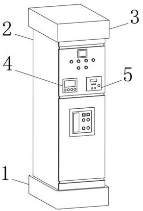
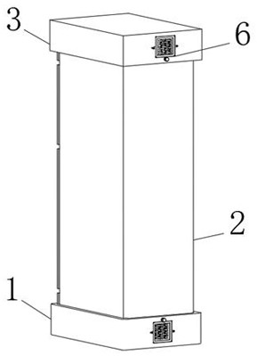
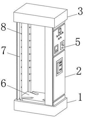
[0027] see Figure 1-9 , the present invention provides a technical solution: a 12kv switch cabinet structure with controllable temperature rise, including a base 1, a cabinet body 2 and a top seat 3, and a current controller 4 and a temperature and humidity controller are fixedly installed on the outside of the cabinet body 2 respectively. The controller 5, the base 1 and the top base 3 are fixedly installed on the bottom and the top of the cabinet body 2 res...


PUM


Abstract

The invention discloses a 12kv switch cabinet capable of controlling the temperature rise, which comprises a bottom base, a cabinet body and a top base, wherein the outer side of the cabinet body is fixedly equipped with a current controller and a temperature and humidity controller, the bottom base and the top base are fixedly installed at the bottom end and the top end of the cabinet body respectively, and both the bottom base and the top base are internally provided with a forced ventilation device. According to the 12kv switch cabinet structure capable of controlling the temperature rise,the design of the ventilation channel of the switch cabinet is optimized, the measure of combining forced air cooling and autonomous ventilation is adopted to promote air convection in the switch cabinet, the current controller is actively started at 70% of the rated current, and the temperature and humidity controller is actively started at 60% of the relative humidity, so that the temperature rise is controlled in a mode that the part which is possibly touched in normal operation is less than 70 DEG C and the temperature rise is less than 30 DEG C, and that the part which cannot be touched in normal operation is less than 80 DEG C and the temperature rise is less than 40 DEG C. Therefore, the temperature rise of the 12kv switch cabinet can be effectively controlled, and thus the 12kv switch cabinet is effectively protected.

Description

technical field [0001] The invention relates to the technical field of 12kv switchgear, in particular to a 12kv switchgear structure with controllable temperature rise. Background technique [0002] The switchgear, especially the 12kV switchgear, is prone to overheating due to various factors, and the internal overheating of the 12kV switchgear has become a common problem in the use of the switchgear. Due to the airtightness of the 12KV switchgear, some heavy load In some areas, there is often the problem of excessive temperature rise of 12KV switchgear. [0003] The temperature rise of the switchgear exceeds the standard, which directly affects the safe and stable operation of the equipment. Moreover, the overheating problem is a continuous development process. If it is not controlled, the degree of overheating will continue to increase, resulting in accelerated aging of the insulating materials in the cabinet, which will endanger electrical equipment. The use safety and s...

Claims


Application Information

Patent Timeline
Patent Type & Authority Patents(China)
IPC IPC(8): H02B1/56H02B1/28
CPCH02B1/28H02B1/565
Inventor 应兵荣方强张庆军李冰峰方健方建峰
Owner ZHEJIANG DISIWEI ELECTRIC
Why Eureka
Eureka Blog
Learn More