Bulb-type LED lamp

a led lamp and bulb-type technology, applied in the field of light-emitting devices, can solve the problems of short lifespan, high energy consumption of lighting devices, and large amount of heat generation, and achieve the effects of enhancing the cooling effect, accelerating the cooling speed, and less material us

Inactive Publication Date: 2011-11-15
CHICONY POWER TECH CO LTD
View PDF5 Cites 24 Cited by
  • Summary
  • Abstract
  • Description
  • Claims
  • Application Information

AI Technical Summary

Benefits of technology

Therefore, in order to solve aforementioned problems, the invention is mainly to provide a bulb-type LED lamp and a cooling structure thereof, which can enhance thermal convection and further promote cooling efficiency.
Compared to prior arts, the invention has following merits. First of all, surrounding air can freely flow among the cooling fins to make heat exchange sufficiently, so the cooling effect is enhanced due to the thermal convection, and the cooling speed is accelerated. In the meantime, the working performance of the bulb-type LED lamp is promoted and less material is used by the cooling structure. Therefore, the manufacturing cost is reduced and the entire weight is lightened, making the invention has a significant economic effect.

Problems solved by technology

However, during the operation when the tungsten filament generates illuminating light, a large amount of heat is also generated.
Therefore, this kind of lighting device is very power-consuming and energy wasting, and has very short lifespan because the tungsten filament is easily burned to black out the incandescent bulb.
However, since the cooling efficiency of the aluminum-extruded cooling seat is decided by the surface area thereof, and because the surrounding air can only make heat exchange with the surface of the aluminum-extruded cooling seat, the cooling efficient is limited and the cooling speed is slow, further influencing the working performance of this kind of bulb-type LED lamp.

Method used


Image

  • Bulb-type LED lamp
  • Bulb-type LED lamp
  • Bulb-type LED lamp

Examples


Embodiment Construction

In cooperation with attached drawings, the technical contents and detailed description of the present invention are described thereinafter according to a preferable embodiment, not used to limit its executing scope. Any equivalent variation and modification made according to appended claims is all covered by the claims claimed by the present invention.

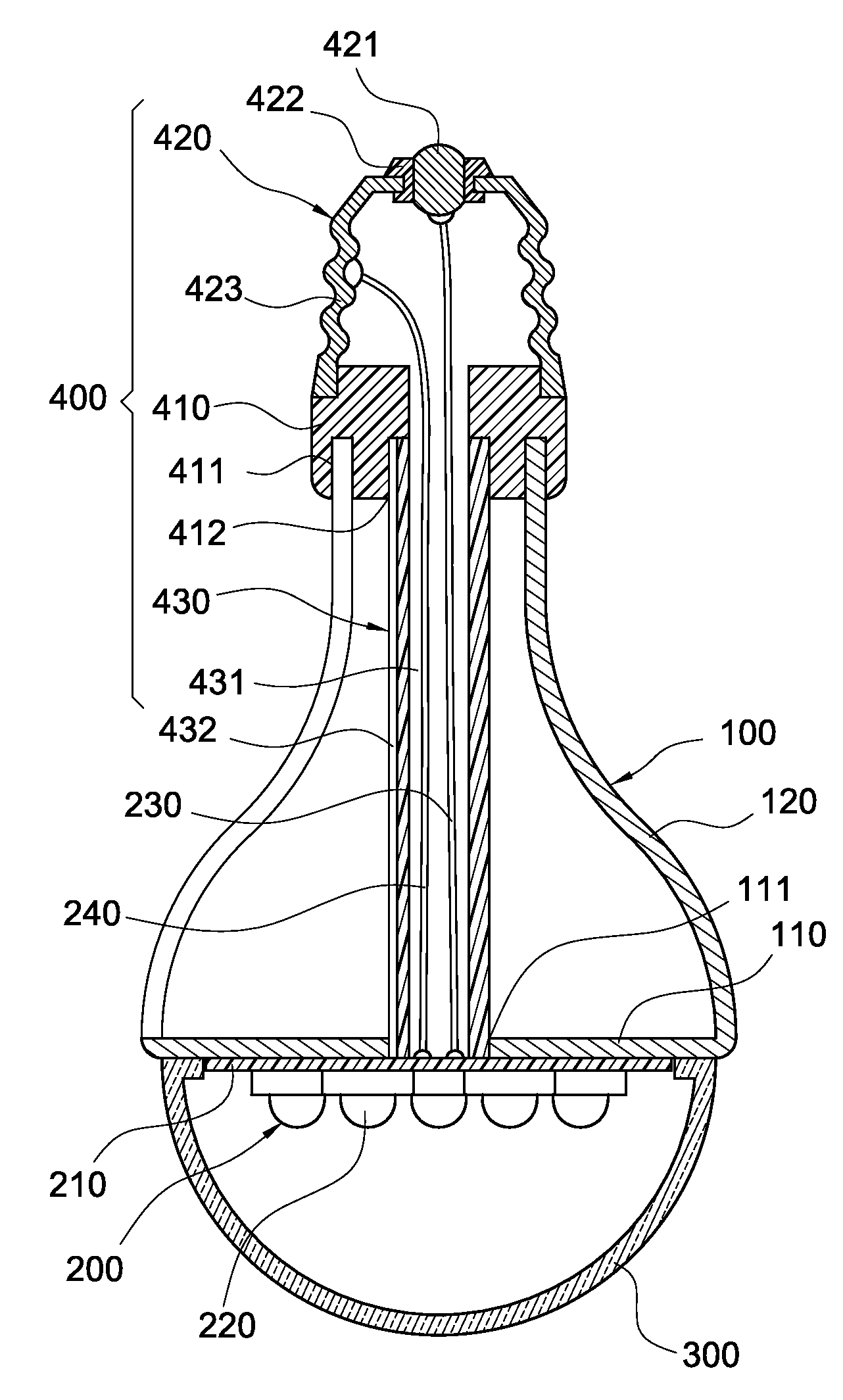
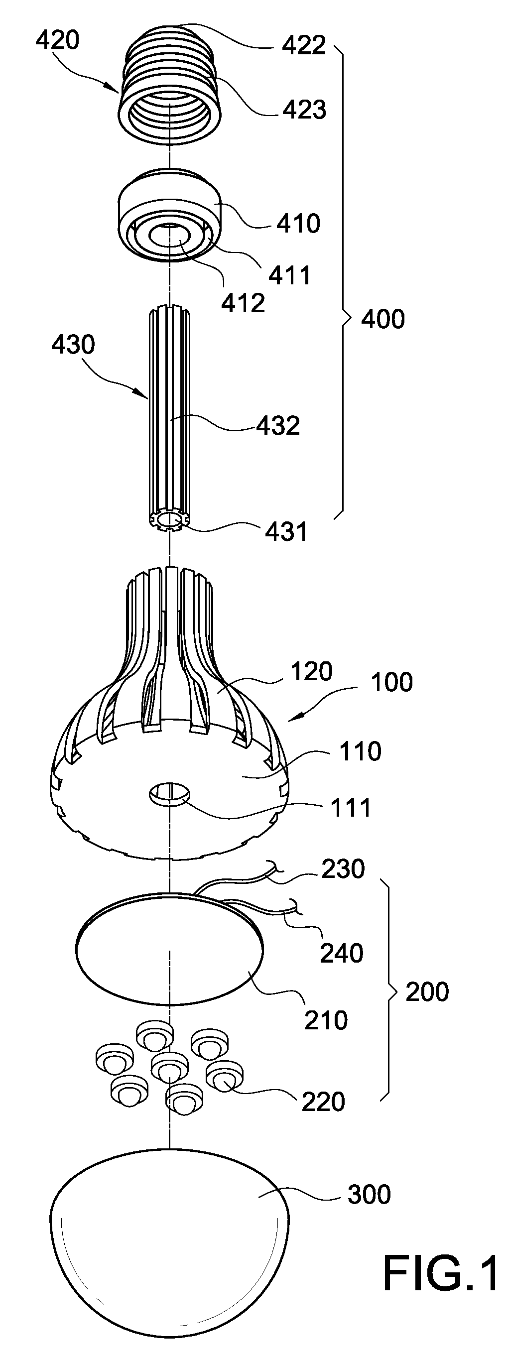
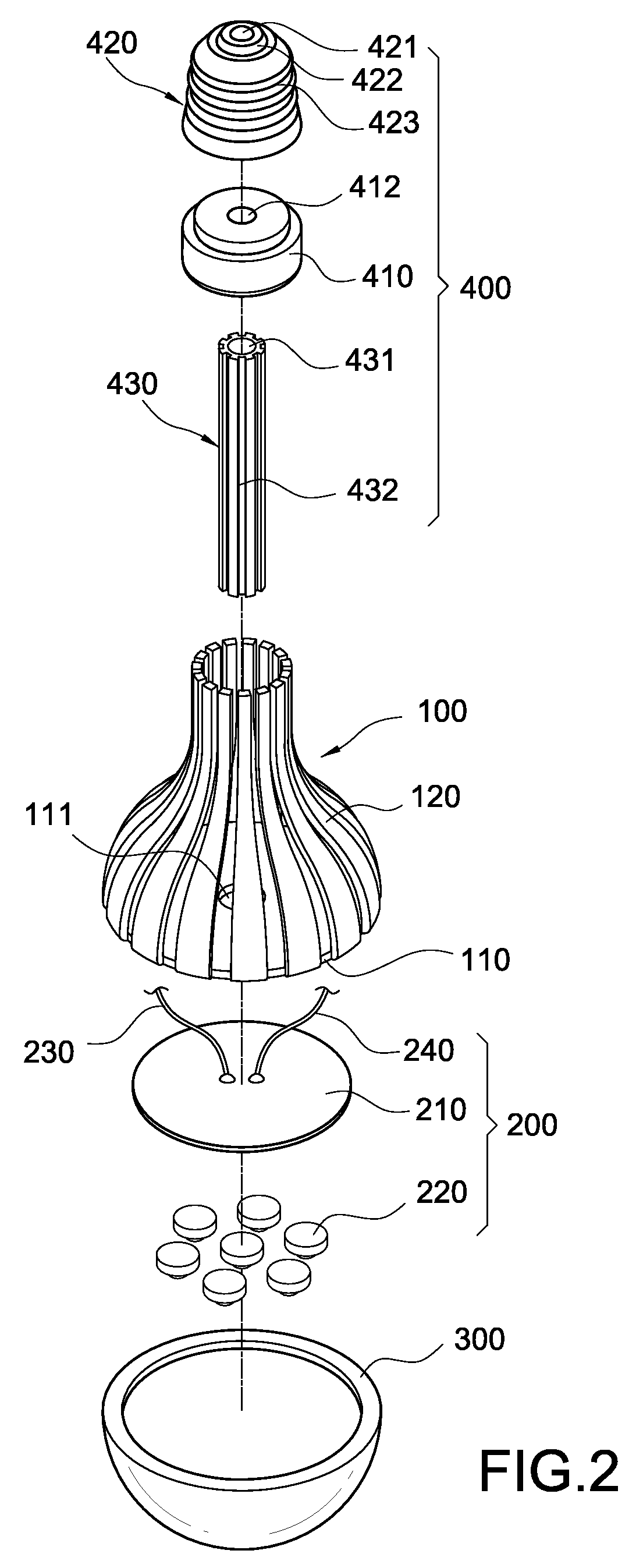
As shown in FIG. 1 through FIG. 4, the invention is mainly to provide a bulb-type LED lamp and a cooling structure thereof, the bulb-type LED lamp including: a cooling structure 100, an LED module 200, a transparent shade 300 and a lamp head 400.

The cooling structure 100 includes a thermally conductive plate 110 and a plurality of cooling fins 120. These cooling fins 120 are entirely configured as a lateral periphery to the thermally conductive plate 110 and are interspaced to each other to be formed a ring-like array around the periphery of the thermally conductive plate 110. The configuration pattern of these cooling fins 120 is desc...


PUM


Abstract

A bulb-type LED lamp includes a cooling structure, an LED module, a transparent shade and a lamp head. The cooling structure includes a thermally conductive plate and a plurality of cooling fins configured by being bended upwardly from a periphery of the thermally conductive plate, and each cooling fins are disposed by being interspaced to each other. The LED module is attached onto a bottom face of the thermally conductive plate. The transparent shade covers the LED module correspondingly and is connected fixedly to the thermally conductive plate. The lamp head is fitted and connected to each cooling fin and electrically connected to the LED module. Thereby, the thermal convection is enhanced and the cooling efficiency is further promoted.

Description

BACKGROUND OF THE INVENTION1. Field of the InventionThe present invention in general relates to a lighting device, in particular, to a bulb-type LED lamp and a cooling structure thereof.2. Description of Prior ArtCommon incandescent bulb takes tungsten filament as lighting source, so the structure is simple, and the arrangement and exchange therefor are very convenient. In the structure of an incandescent bulb, a tail end of the spherical shade is usually fixedly connected an adapter, on which there are threads adapted to be screwed in a common bulb socket. When power is conducted, the tungsten filament arranged in the shade can emit heat and light, and the light shines outwardly via the shade to reach a lighting purpose. However, during the operation when the tungsten filament generates illuminating light, a large amount of heat is also generated. Therefore, this kind of lighting device is very power-consuming and energy wasting, and has very short lifespan because the tungsten fil...

Claims


Application Information

Patent Timeline
Patent Type & Authority Patents(United States)
IPC IPC(8): H01J61/52F21V29/02
CPCF21K9/135F21V29/83F21V29/74F21V3/00F21V23/002Y10S362/80F21V29/507F21Y2101/02F21K9/232F21Y2115/10
Inventor LAI, CHYI-LANG
Owner CHICONY POWER TECH CO LTD
Why Eureka
Try Eureka