

Glass fiber tank furnace structure and glass smelting method
A glass fiber and tank kiln technology, which is applied in glass manufacturing equipment, glass furnace equipment, manufacturing tools, etc., can solve the problems of high energy consumption, roof collapse, low heat utilization rate, etc., and achieve high heat transfer efficiency and corrosion resistance Small, long-lasting effect
- Summary
- Abstract
- Description
- Claims
- Application Information
AI Technical Summary
Problems solved by technology
Method used
Image

Examples
Embodiment 1
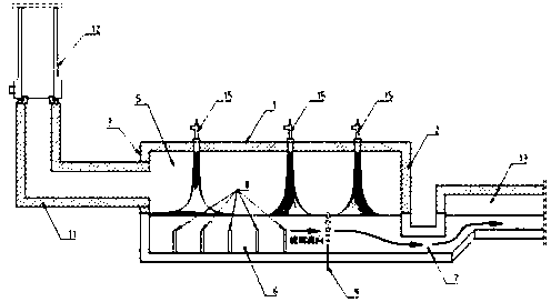
[0026] refer to Figure 1-4 , to further illustrate the present invention:
[0027] The structure of the glass fiber tank kiln includes two parts, the melting part 5 and the passage 13. The melting part 5 has a feeding pool 14 for supplying glass raw materials, and a melting pool 6 for receiving incoming materials and forming molten glass. The glass liquid separating device between the melting pool 6 and the passage 13 is a liquid flow hole 7. The upper part of the melting pool 6 has a large bridge 1, Breast walls 4 on both sides, front face wall 3 , rear face wall 2 and flue 11 . The melting pool 6 is divided into A zone (raw meal zone), B zone (foam zone) and C zone (clarification zone) according to the process.
[0028] At least one burner 15 is respectively installed in areas A, B, and C of the melting pool, and the installation positions are respectively on the large wall 1 above the areas A, B, and C. The flame is sprayed toward the glass batch material, and the two T...
Embodiment 2
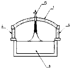
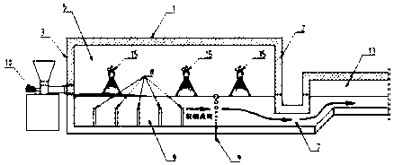
[0035] refer to Figure 5-7 , to further illustrate the present invention:
[0036] The structure of the glass fiber tank kiln includes two parts, the melting part 5 and the passage 13. The melting part 5 has a melting pool 6 that accepts incoming materials and forms molten glass. The glass liquid separating device between the melting pool 6 and the passage 13 is a flow hole 7. The upper part of the melting pool 6 has a large wall 1, breast walls 4 on both sides, and a front wall. 3. The back wall 2 and the flue 11. The melting pool 6 is divided into A zone (raw meal zone), B zone (foam zone) and C zone (clarification zone) according to the process.
[0037] At least one burner 15 is respectively installed in areas A, B, and C of the melting pool, and the installation positions are respectively on the parapet 4 above the areas A, B, and C. The angle between the parapet wall is 58°, and the angle between it and the front or back wall is 0°.
[0038] There are five rows of e...
Embodiment 3
[0043] Refer to attached Figure 1-7 :
[0044] The method for melting glass by applying the above-mentioned fiberglass tank kiln structure comprises the following steps:
[0045] Step 1, setting at least one burner above the melting pool of the fiberglass tank kiln, on the large wall or parapet;
[0046] Step 2, supply gaseous oxidant and gaseous or liquid or solid fuel fluid to the burner;
[0047] Step 3, spray the flame of the burner to the glass batch, the spray angle is 0-80° with the breast walls on both sides, and the angle with the front wall or the back wall is 0°, and the speed of the flame is 30-100m / s.
[0048] The technical idea of the present invention is: make the burner 15 spray fuel and oxygen against the glass batch material and the glass liquid, make the high temperature part of the end of the flame close to or even touch the glass batch material and the glass liquid, reduce the flame and the glass batch material and the The distance between the molt...
PUM
 Abstract
Description
Claims
Application Information