

Heat accumulated type lead-melting furnace
A heat storage type, lead-melting furnace technology, applied in furnaces, crucible furnaces, waste heat treatment, etc., can solve the problems of only 3 to 6 months of service life, short service life of lead pots, and large exhaust smoke loss, etc., to reduce burning damage, increase the flame fullness, and eliminate the effects of high temperature areas
Inactive Publication Date: 2009-08-26
ZHUZHOU FLASHLIGHT IND FURNACE
View PDF0 Cites 23 Cited by
- Summary
- Abstract
- Description
- Claims
- Application Information
AI Technical Summary
Problems solved by technology
[0003] 1) The unit gas consumption is high, and the unit consumption of electric lead gas per ton is about 180-240m 3 ;
[0004] 2) The thermal efficiency is low, only about 10%;
[0005] 3) The service life of the lead pot is short, generally only 3 to 6 months;
[0006] 4) The smoke exhaust loss is large, and the sensible heat loss taken away by the flue gas is as high as 50% to 60%;
[0007] 5) Chemical incomplete combustion loss as high as 20% to 30%
Method used
View moreImage
Smart ImageViewing Examples

Examples
Embodiment Construction
[0024] The present invention will be described in further detail below in conjunction with the embodiments and accompanying drawings.
Login to View More PUM
 Abstract
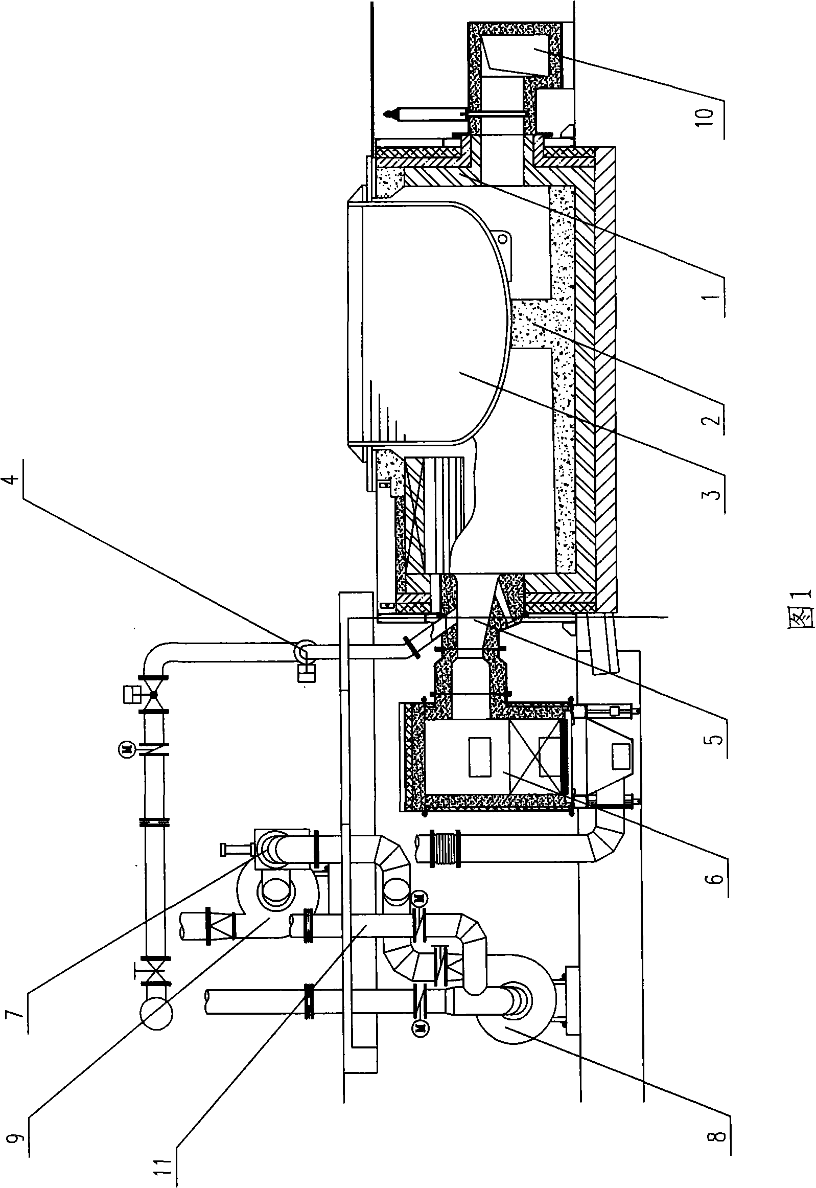
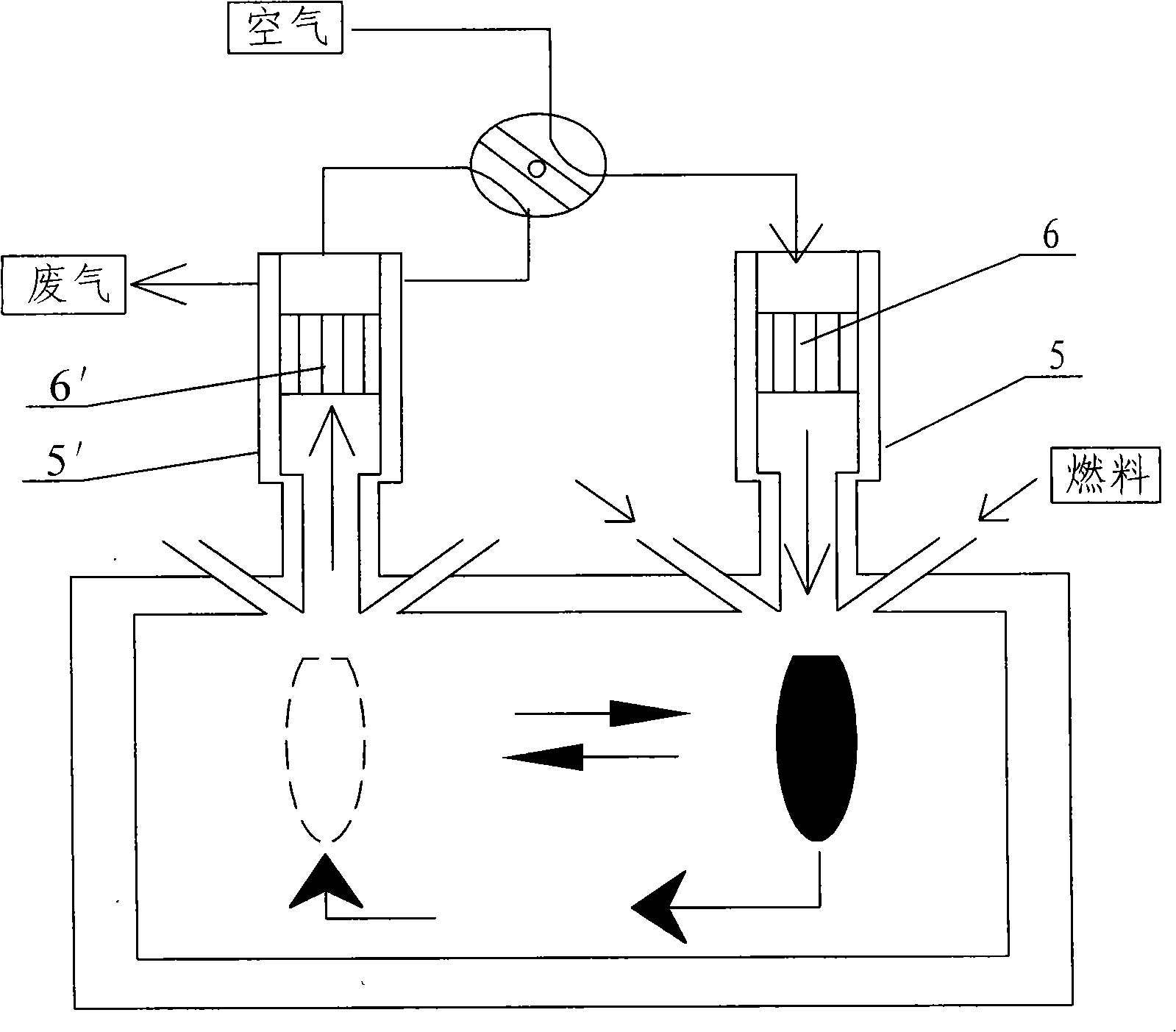
The invention discloses a heat accumulated type lead-melting furnace, which includes a furnace body, a heat accumulated type combustion system and a automatic combustion control system, wherein the heat accumulated type combustion system mainly includes heat accumulated type burners, a combustion gas pipeline, a smoke evacuation system and a air supplying system, the heat accumulated type burners are arranged at one side of the furnace body in pair, a main pipeline of the combustion gas pipeline extends to heat accumulated type burner tips of the two heat accumulated type burners through a combustion gas reversing valve and two branch pipelines, heat accumulated bodies of the heat accumulated type burners are respectively connected with a blower exhaust pipeline of the air supplying system and a draught fan smoking pipeline of the smoke evacuation system through the pipeline and a triple valve, and the triple valve is used for controlling air inlet or smoke evacuation. The invention can reduce fuel consumption, save energy, reasonably control combustion status in the furnace and increase operation security performance of the furnace.
Description
technical field [0001] The invention relates to metal smelting equipment, in particular to a regenerative lead melting furnace used in the lead smelting process. Background technique [0002] The main technological process of the existing lead smelting process is as follows: lead ore smelting—crude lead—crude lead refining to prepare anode—electrolysis—cathode lead sheet melting and casting—lead ingot. At present, major domestic lead smelting manufacturers use lead melting pots for smelting in crude lead refining, cathode lead casting, and cathode manufacturing. According to the difference in use, they can be divided into anode pots, cathode pots, electric lead pots, and alloy pots. etc., collectively referred to as the melting lead pot here. Its forms all use steel crucibles, which are heated by solid, gas, and liquid fuels for indirect melting. During the use of the above-mentioned lead-melting pots, there are generally defects such as high exhaust gas temperature, poor ...
Claims
Login to View More Application Information
Patent Timeline
 IPC IPC(8): F27B14/00F27B14/14F27B14/20F23D14/00F23D14/48F23D14/66F23D14/76F27D17/00
CPCY02E20/34
Inventor汪洋洋蒋绍坚艾元方鲁志昂沈维民贺新华张新根
OwnerZHUZHOU FLASHLIGHT IND FURNACE