Heat storage type combustor powered by liquid fuel

A liquid fuel and burner technology, applied in the directions of burners, combustion methods, combustion types, etc., can solve the problems of uneven distribution, reduced combustion efficiency, and high exhaust gas temperature, eliminate local high temperature areas, reduce heat loss, and improve The effect of combustion temperature

Active Publication Date: 2014-11-05
XI AN JIAOTONG UNIV
View PDF10 Cites 0 Cited by
  • Summary
  • Abstract
  • Description
  • Claims
  • Application Information

AI Technical Summary

Problems solved by technology

[0002] At present, most burners still use space combustion as the main method, which has the following disadvantages: 1. Low-temperature air combustion, the temperature of the combustion chamber is low and unevenly distributed, and there are local high-temperature areas, which affect the service life of the boiler
Excessive local temperature produces NOx and cancer-curing organic substances, which are prone to black smoke and cause environmental pollution
2. The mixture of fuel and air is not uniform enough, incomplete combustion produces a large amount of CO and the combustion efficiency decreases
3. The exhaust gas temperature is high, taking away a lot of heat energy, and the combustion efficiency is low
Compared with traditional burners, the burners they studied still use nozzles to initially vaporize the liquid, and the adaptability and stability are not good enough

Method used


Image

  • Heat storage type combustor powered by liquid fuel
  • Heat storage type combustor powered by liquid fuel

Examples


Embodiment Construction

[0015] The present invention will be described in further detail below in conjunction with the accompanying drawings.

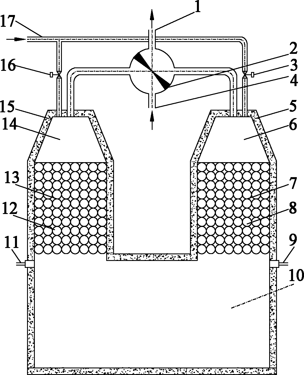
[0016] see figure 1 , the present invention includes two sets of regenerative combustors with the same structure, the regenerative combustors include top-down air-fuel premix chambers 6, 14 and pellet regenerators stacked with phase change regenerative pellets 8, 12 7, 13, the two regenerators are respectively connected with the combustion chamber 10 at the lower end, and the outer sides of the regenerator and the combustion chamber 10 are provided with insulation layers 5, 15, and are arranged in the combustion chamber 10 at the lower end of the two regenerators. There are igniters 9 and 11, and the upper ends of the two same regenerative combustion chambers are respectively connected with the liquid fuel supply pipe 17, the air-smoke two-position four-way valve 2 with the air inlet 4 and the smoke outlet, and the liquid fuel supply pipe 17 are provided wit...


PUM


Abstract

A heat storage type combustor powered by liquid field comprises two heat storage combustion chambers and an air / flue gas four-way reversing valve. The structures of the two heat storage combustion chambers are identical, and each heat storage combustion chamber consists of an air-fuel premixing chamber, a ball stacking heat storage chamber, a combustion chamber, a lighter, an air supply pipe and a liquid fuel supply pipe. The combustor is provided with combustion-supporting air inlets and liquid fuel inlets, combustion-supporting air and liquid fuel are mixed in the premixing chambers, run through the ball stacking heat storage chambers and are ignited in the combustion chambers, and the two combustion chambers are periodically alternately used for combustion and flue gas exhaust. Stacked balls of the heat storage chambers are ceramic balls, phase-change materials with the phase-change temperature higher than the boiling point of the liquid fuel are filled in the ceramic balls. The combustor is characterized in that the liquid fuel is more sufficiently mixed with the air after being vaporized by the heat storage chambers, and combustion temperature and combustion efficiency are enhanced. The combustion chambers realize combustion in a reversing manner, local high-temperature areas of insides of the combustion chambers are eliminated, the temperature inside each combustion chamber is distributed more uniformly, heat stability of combustion is improved, and the service life of the combustor is prolonged.

Description

technical field [0001] The invention relates to a burner, in particular to a liquid fuel regenerative burner. Background technique [0002] At present, most burners still use space combustion as the main method, which has the following disadvantages: 1. Low-temperature air combustion, the temperature of the combustion chamber is low and unevenly distributed, and there are local high-temperature areas, which affect the service life of the boiler. Excessive local temperature produces NOx and cancer-curing organic substances, which are prone to black smoke and cause environmental pollution. 2. The mixing of fuel and air is not uniform enough, incomplete combustion produces a large amount of CO and the combustion efficiency decreases. 3. The exhaust gas temperature is high, which takes away a lot of heat energy, and the combustion efficiency is low. In response to the above problems, domestic and foreign scholars have done a lot of research on the technology of adding porous m...

Claims


Application Information

Patent Timeline
Patent Type & Authority Patents(China)
IPC IPC(8): F23D11/02F23D11/40F23D11/44
Inventor 高怀斌屈治国卢天健陶文铨
Owner XI AN JIAOTONG UNIV
Why Eureka
Try Eureka