Light emitting diode lamp

a technology of light-emitting diodes and lamps, which is applied in the field of lamps, can solve the problems of increasing manufacturing costs and the inability to effectively reduce the thickness of lamps, and achieves the effects of simple structure, favorable heat dissipation efficiency, and uniform light-emitting

Inactive Publication Date: 2012-09-20
CORETRONIC
View PDF12 Cites 26 Cited by
  • Summary
  • Abstract
  • Description
  • Claims
  • Application Information

AI Technical Summary

Benefits of technology

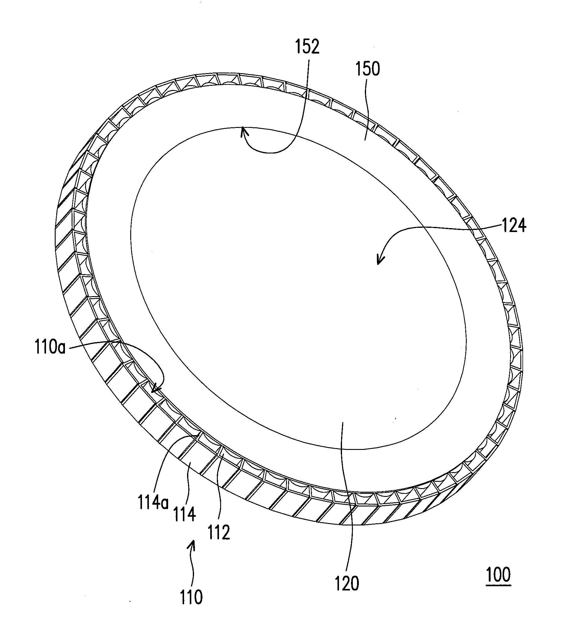
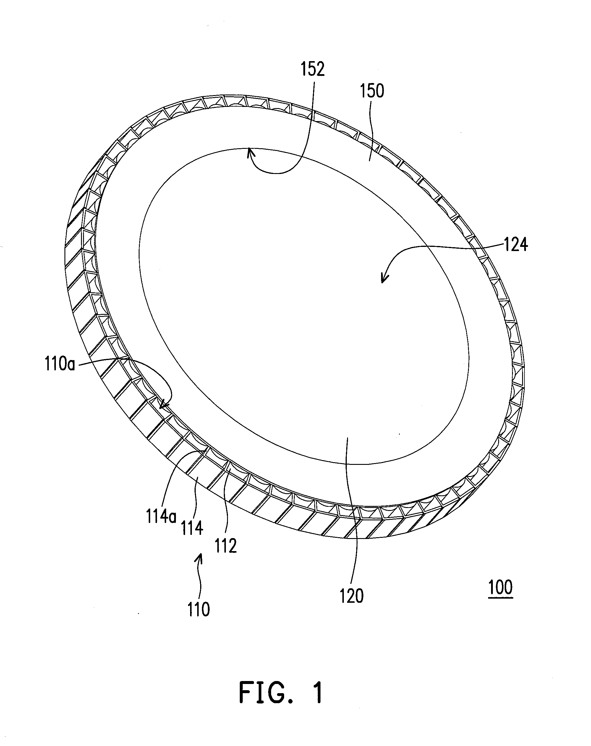
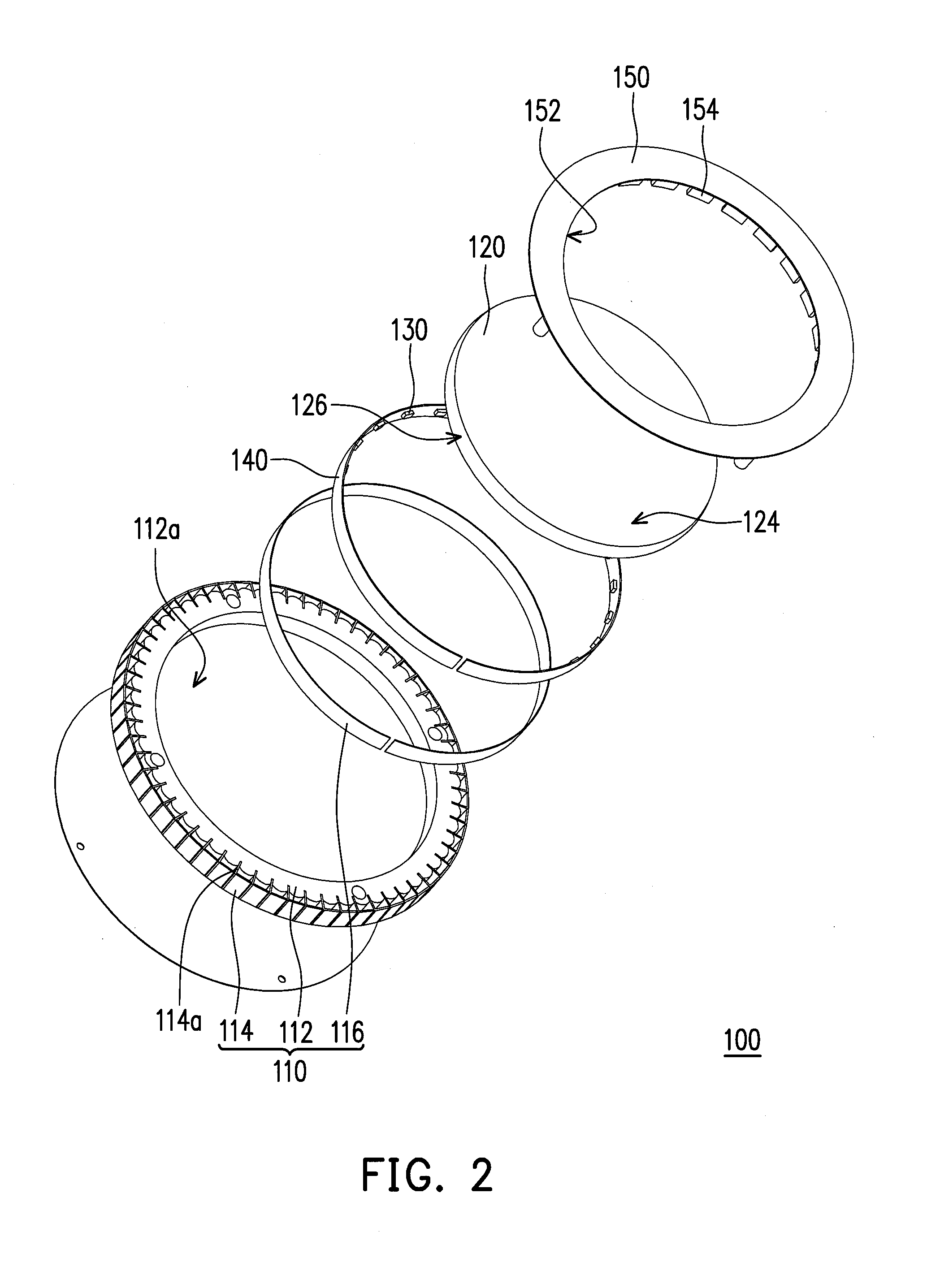
[0008]The invention is directed to an LED lamp that has favorable heat dissipation efficiency, light emission uniformity, and the simple structure.
[0011]Based on the above, according to the previous embodiments of the invention, the heat dissipation element is connected to the heat-conducting base through the connection portion, and the heat dissipation element is distant from the heat-conducting base. Thereby, the heat dissipation area could be expanded, and the distance between the heat dissipation element and the heat-conducting base is conducive to the improvement of air convection and heat dissipation efficiency. Moreover, after the light beam emitted by the LED light sources enters the circular LGP, the light beam could be reflected by the annular trenches of the circular LGP and emitted from the bottom surface of the circular LGP, such that the light patterns are circularly symmetric, and that light emission uniformity could be achieved. It is not necessary to add optical elements (e.g., the prism) to the LED lamp for condensing light. As a result, the LED lamp could have simpler structure, which leads to simplification of the manufacturing process and reduction of the manufacturing costs.

Problems solved by technology

However, excessive elements lead to the difficulty in assembly and the increase in manufacturing costs, and the thickness of the lamp could not be effectively reduced.

Method used


Image

  • Light emitting diode lamp
  • Light emitting diode lamp
  • Light emitting diode lamp

Examples


Embodiment Construction

[0020]In the following detailed description of the embodiments, reference is made to the accompanying drawings which form a part hereof, and in which are shown by way of illustration specific embodiments in which the invention may be practiced. In this regard, directional terminology, such as “top,”“bottom,”“front,”“back,”“left,”“right,” etc., is used with reference to the orientation of the Figure(s) being described. The components of the invention can be positioned in a number of different orientations. As such, the directional terminology is used for purposes of illustration and is in no way limiting. On the other hand, the drawings are only schematic and the sizes of components may be exaggerated for clarity. It is to be understood that other embodiments may be utilized and structural changes may be made without departing from the scope of the invention. In addition, it is to be understood that the phraseology and terminology used herein are for the purposes of description and s...


PUM


Abstract

A light emitting diode (LED) lamp includes a heat dissipation module, a circular light guide plate (LGP), and LED light sources. The heat dissipation module includes a heat dissipation element and a heat-conducting base that has a containing concave. The heat dissipation element connecting and surrounding the heat-conducting base is distant from the circumference of the heat-conducting base. The circular LGP in the containing concave has a top surface, a bottom surface, and an annular side surface. The top surface faces the heat-conducting base and has concentric annular trenches. The LED light sources are configured in the containing concave and face the annular side surface. The LED light sources are suitable for emitting a light beam which is capable of passing through the annular side surface to enter the circular LGP and capable of being reflected by the annular trenches and emitted from the bottom surface.

Description

CROSS-REFERENCE TO RELATED APPLICATION[0001]This application claims the priority benefit of Taiwan application serial no. 100108516, filed on Mar. 14, 2011. The entirety of the above-mentioned patent application is hereby incorporated by reference herein and made a part of this specification.BACKGROUND OF THE INVENTION[0002]1. Field of the Invention[0003]The invention relates to a lamp. More particularly, the invention relates to a light emitting diode (LED) lamp that has a heat dissipation module.[0004]2. Description of Related Art[0005]An LED is a semiconductor element, and a material of a light emitting chip of the LED mainly includes a compound selected from groups III-V chemical elements, such as gallium phosphide (GaP) or gallium arsenide (GaAs). The light emitting principle of the LED lies in the conversion of electric energy into light. Specifically, after a current is applied to the compound semiconductor, the LED releases an excess of energy in a form of light through the ...

Claims


Application Information

Patent Timeline
Patent Type & Authority Applications(United States)
IPC IPC(8): F21V8/00
CPCY10S362/80F21S8/03F21Y2101/02F21Y2103/022F21V2200/20G02B6/0045G02B6/0068G02B6/0085G02B6/0038F21Y2103/33F21Y2115/10
Inventor WEI, CHIA-HUNGLIN, SHENG-HUNGHWANG, JUNG-MIN
Owner CORETRONIC
Why Eureka
Try Eureka