Thermal deformation automatic compensation mechanism for screw rod and machine tool

An automatic compensation and thermal deformation technology, applied in the field of mechanical processing, can solve problems such as many structural restrictions, difficult control of machine tool costs, and poor versatility

Inactive Publication Date: 2014-07-16
SANY GRP
View PDF4 Cites 0 Cited by
  • Summary
  • Abstract
  • Description
  • Claims
  • Application Information

AI Technical Summary

Problems solved by technology

These two methods are to control the temperature of the machine tool at the heat source. The first method is relatively difficult to control the cost of the machine tool because the optional range of machine tool parts and materials is limited; the second method needs to add more components to realize the function. Due to the limitations of the structure of the machine tool itself, and the effect is not very ideal, the application limitations of these two methods are relatively large
Temperature compensation is a thermal error compensation technology. As a feedback technology, it measures the errors that have occurred during CNC machining by various means, and then performs error compensation calculations based on the established error compensation model to eliminate the effects of thermal deformation. At present, this method is the main means to eliminate thermal deformation of machine tools and improve machining accuracy, but this method requires the participation of CNC system. Since different error compensation models are required for different types of machine tools, this method has poor versatility

Method used


Image

  • Thermal deformation automatic compensation mechanism for screw rod and machine tool
  • Thermal deformation automatic compensation mechanism for screw rod and machine tool
  • Thermal deformation automatic compensation mechanism for screw rod and machine tool

Examples


Embodiment Construction

[0021] It should be noted that, in the case of no conflict, the embodiments in the present application and the features in the embodiments can be combined with each other. The present invention will be described in detail below with reference to the accompanying drawings and examples.

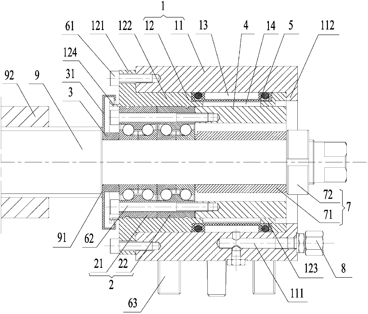
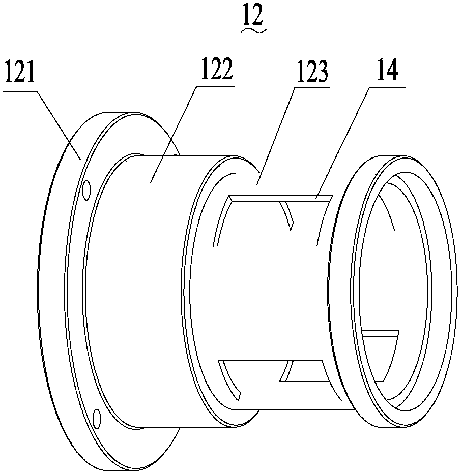
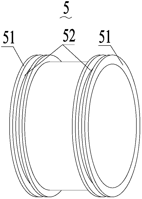
[0022] see Figure 1 to Figure 3 , shows the structure of a preferred embodiment of the automatic compensation mechanism for thermal deformation of the lead screw provided by the present invention. As shown in the figure, the screw thermal deformation automatic compensation mechanism at least includes: a fixed mounting base 1 , a bearing 2 , a first axial limiter 3 , a ferrule 4 and an elastic clamping member 5 . It can be seen from the figure that the lead screw 9 is provided with a lead screw nut 92, and at least one end of the lead screw 9 is supported by the lead screw thermal deformation automatic compensation mechanism.

[0023] Specifically, the fixed installation base 1 is installed o...


PUM


Abstract

The invention provides a thermal deformation automatic compensation mechanism for a screw rod and a machine tool. The thermal deformation automatic compensation mechanism for the screw rod comprises a fixed mounting seat, a bearing, a first axial limiting part, a ferrule and an elastic clamping part, wherein the fixed mounting seat is mounted on a fixed pivot; an annular chamber is formed between the fixed mounting seat and the screw rod; the bearing is mounted in the annular chamber and is sleeved on the screw rod; the first axial limiting part is mounted on the screw rod and is arranged close to the first end of the bearing; the first axial limiting part is in supported press contact with an inner ring of the bearing; the ferrule is sleeved in the annular chamber and is arranged close to the second end of the bearing; the ferrule is fixedly connected with an outer ring of the bearing; a pressure chamber is arranged in the fixed mounting seat and is connected with a pressure oil source through an oil path; a hole is formed in the fixed mounting seat; the first end of the hole is communicated with the pressure chamber; the second end of the hole corresponds to the outer circumferential wall of the ferrule; and the elastic clamping part is positioned in the pressure chamber and is converted on a hole shoulder of the hole, so that the pressure chamber is separated from the hole. The technical scheme adopted by the invention has the advantages of simple structure, strong generality and capability of effectively reducing the thermal error of the machine tool.

Description

technical field [0001] The invention relates to the field of mechanical processing, and more specifically relates to an automatic compensation mechanism for thermal deformation of a lead screw and a machine tool. Background technique [0002] Thermal error is the largest error source of CNC machine tools, accounting for 40%-70% of the total error of the machine tool, so reducing thermal error is the most effective way to reduce machine tool error. At present, there are generally three ways to reduce the thermal deformation of machine tools: one is to improve the machine tool mechanism, the other is temperature control, and the third is temperature compensation. Improving the structure of the machine tool means that when designing the machine tool, the material of the components is reasonably selected according to the coefficient of thermal expansion, and the direction of thermal deformation and thermal error is controlled, so as to effectively prevent the thermal deformation...

Claims


Application Information

Patent Timeline
Patent Type & Authority Patents(China)
IPC IPC(8): B23Q23/00
Inventor 张维磊李强杨刚文
Owner SANY GRP
Why Eureka
Try Eureka