Implementation method of automatic compensation for thermal deformation of machine tool

A technology of automatic compensation and realization method, applied in automatic control devices, metal processing mechanical parts, metal processing and other directions, can solve the problems of incompatibility, long development cycle, low thermal compensation accuracy, etc., to reduce development costs and shorten development cycles. , the effect of high compensation accuracy

Inactive Publication Date: 2010-08-18
四川普什宁江机床有限公司
View PDF2 Cites 46 Cited by
  • Summary
  • Abstract
  • Description
  • Claims
  • Application Information

AI Technical Summary

Problems solved by technology

[0006] However, the above method, on the one hand, does not carry out multiple corrections to the obtained mathematical model, and cannot truly reflect the actual situation of the thermal deformation of the machine tool, so that t

Method used


Image

  • Implementation method of automatic compensation for thermal deformation of machine tool
  • Implementation method of automatic compensation for thermal deformation of machine tool
  • Implementation method of automatic compensation for thermal deformation of machine tool

Examples


Embodiment 1

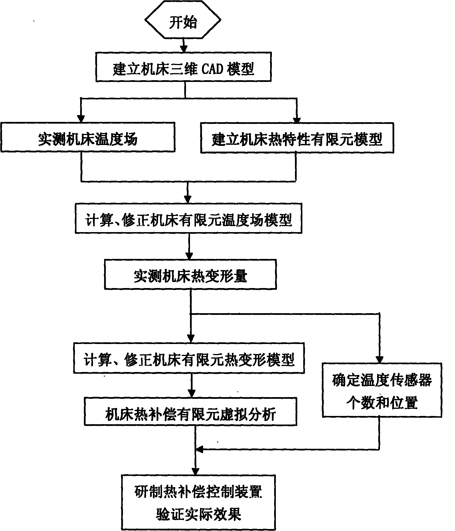
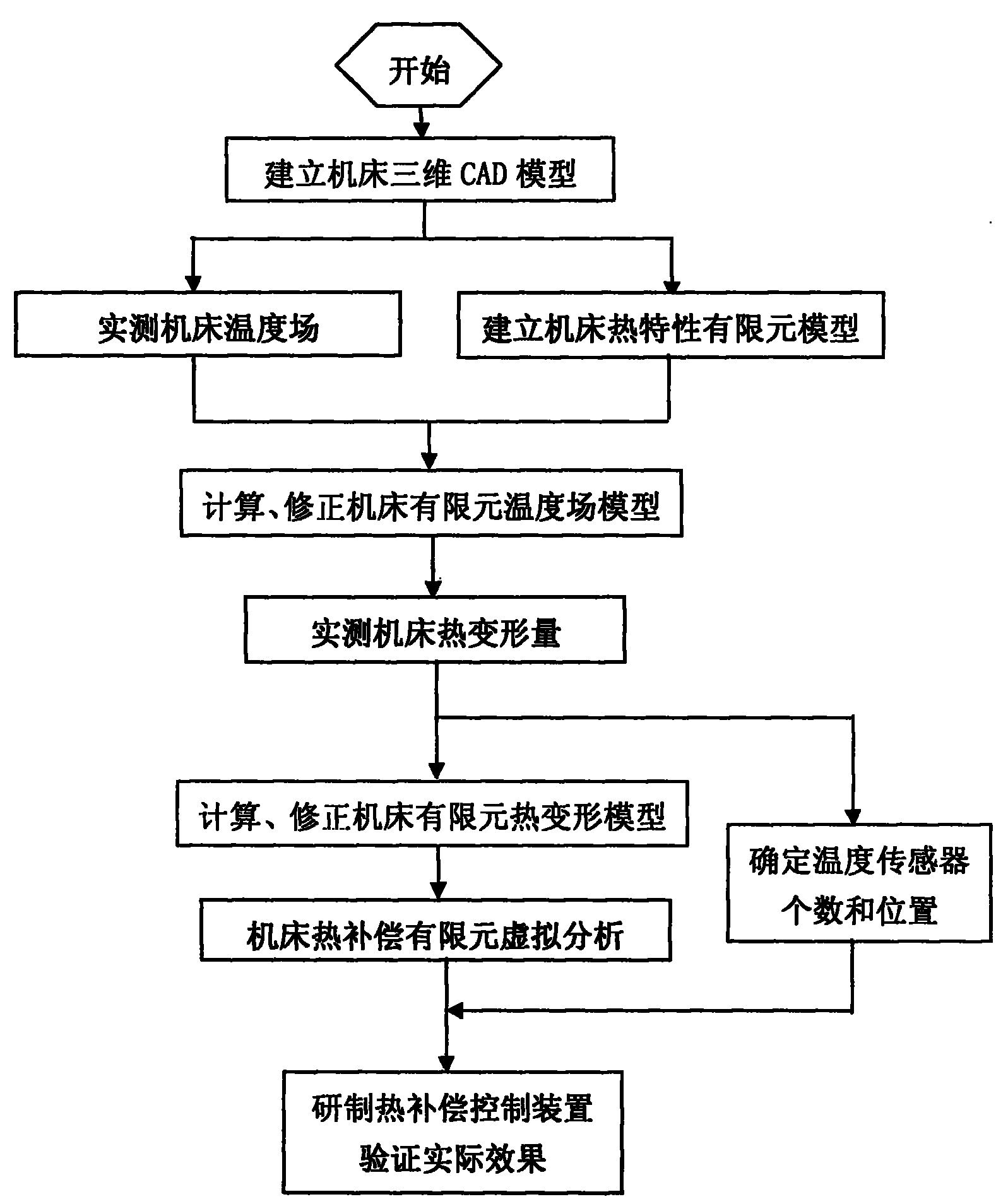
[0038] A method for realizing automatic compensation of thermal deformation of a machine tool adopts an advanced technical scheme based on the combination of a thermal imager, a high-precision position measuring instrument, a temperature measuring instrument and finite element analysis technology. The implementation process is divided into: establishment of the finite element model of the machine tool; detection of the actual temperature field and thermal deformation of the machine tool; correction of the finite element model of the temperature field and thermal deformation of the machine tool; finite element virtual analysis of the thermal compensation of the machine tool; development of the thermal compensation control device and its actual effect Verification and other 5 stages. It includes the following steps:

[0039] 1) Establish a three-dimensional CAD model of the machine tool;

[0040] 2) Measure the temperature field of the machine tool;

[0041] 3) Establish a fin...

Embodiment 2

[0049] On the basis of Embodiment 1, the establishment of the three-dimensional CAD model of the machine tool is based on the design drawing of the machine tool parts, using three-dimensional design software such as Solidedge, to establish the three-dimensional CAD part models of the various parts of the machine tool, and assemble them into the overall CAD of the machine tool parts model, and then assemble the overall CAD model of each component into the overall CAD model of the machine tool. The actual measurement of the temperature field of the machine tool is to use the thermal imager to test the machine base, bed, column, The temperature field distribution map of the headstock, spindle and other components, and save it in JPG (or other) graphic file format. The establishment of the finite element model of the thermal characteristics of the machine tool is through the interface of the 3D modeling software such as Solidedge and the finite element analysis software such as AN...


PUM


Abstract

The invention discloses an implementation method of automatic compensation for thermal deformation of a machine tool, which comprises the following steps: (1) establishing a three-dimensional CAD model of the machine tool; (2) actually measuring the temperature field of the machine tool; (3) establishing a thermal characteristic finite element model of the machine tool; (4) calculating and correcting a finite element temperature field model; (5) actually measuring the thermal deformation of the machine tool; (6) determining the number and positions of temperature sensors; (7) calculating and correcting a finite element thermal deformation model of the machine tool; and (8) virtually analyzing the thermal compensation finite element of the machine tool. The method corrects the finite element temperature field and the thermal deformation model of the machine tool, so that the established finite element model of the machine tool can truly reflect the practical situation of the thermal deformation of the machine tool; and thus, the invention has the advantages of high compensation precision and good stability. In the method, multiple thermal compensation testing processes on the machine tool are completed by a computer through virtual analysis, thereby shortening the development cycle and reducing the development cost.

Description

technical field [0001] The invention relates to the related technical field of machine tool manufacturing, in particular to a method for realizing automatic compensation of machine tool thermal deformation. Background technique [0002] With the development of machine tool manufacturing technology in the direction of high speed and high precision, thermal deformation automatic compensation technology, as an important means to improve the dynamic precision and stability of CNC machine tools, has been applied more and more, and the realization methods are also diversified. Since the method of automatic temperature detection and heating (or cooling) compensation has significant effect and economy, it is a thermal compensation method widely used in machine tools. [0003] The method is to set temperature sensors on some sensitive positions of the machine tool that cause thermal deformation, and set heating elements (or take cooling measures for heat-generating parts) on other re...

Claims


Application Information

Patent Timeline
IPC IPC(8): B23Q15/18
Inventor 曹星际姜华
Owner 四川普什宁江机床有限公司
Why Eureka
Try Eureka