

Vehicular control apparatus and method
a technology of vehicle behavior and control apparatus, which is applied in the direction of brake systems, braking components, transportation and packaging, etc., can solve the problems of accelerating performance of the vehicle, and affecting the comfort of the occupant in the vehicle, etc., and achieves the effect of reducing the function of the vehicle behavior control apparatus
- Summary
- Abstract
- Description
- Claims
- Application Information
AI Technical Summary
Benefits of technology
Problems solved by technology
Method used
Image

Examples
first embodiment
[0041][First Embodiment]
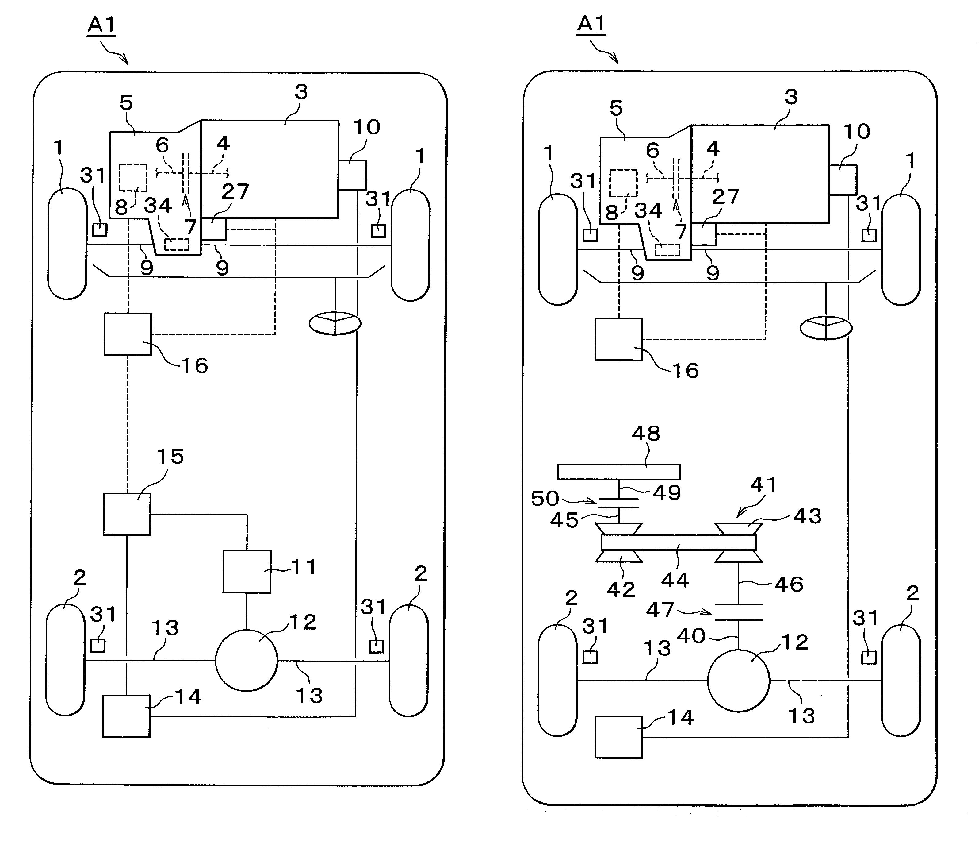
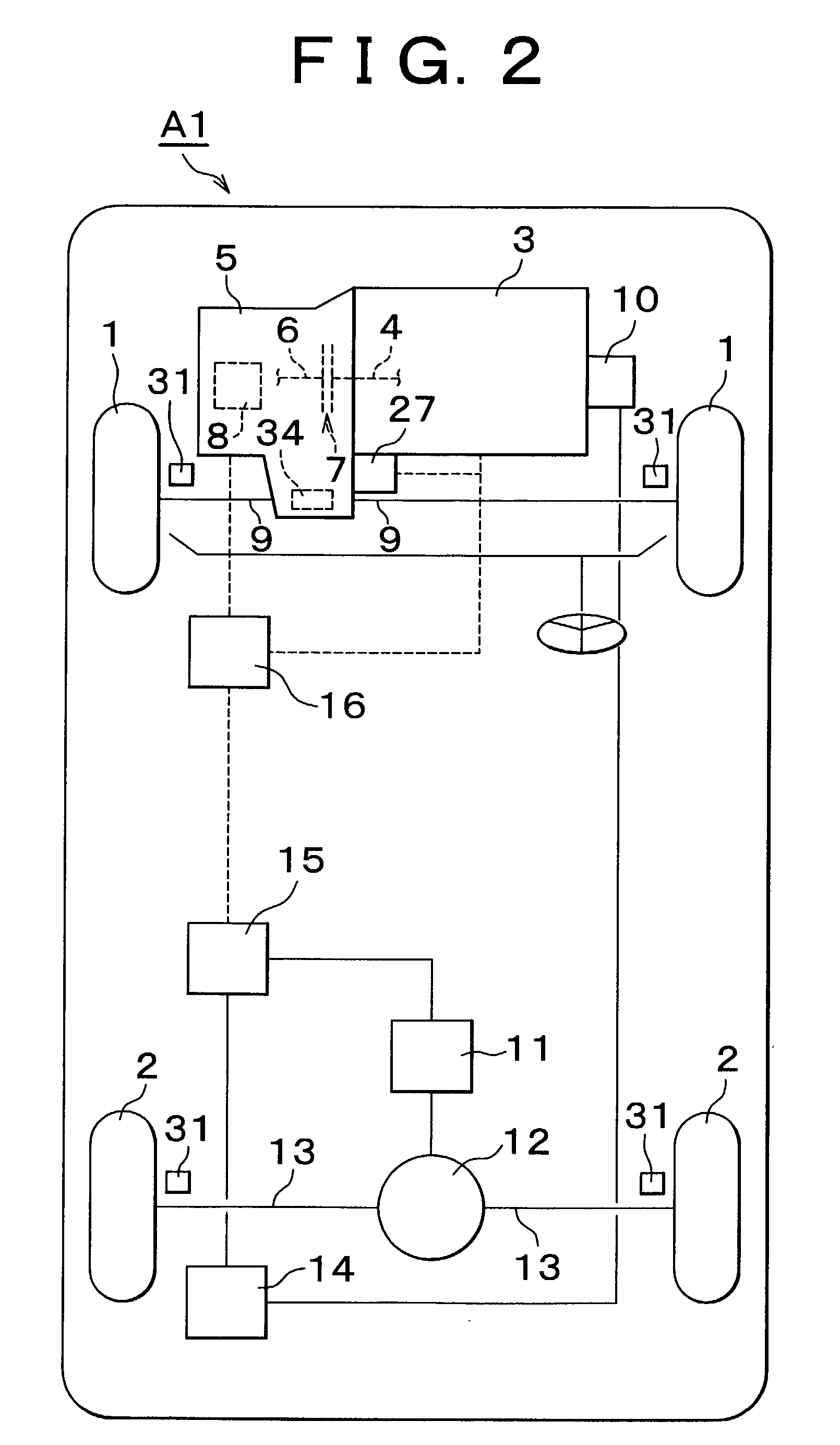
[0042]A first embodiment of the invention will be described below with reference to drawings. FIG. 2 is a conceptual diagram illustrating an exemplary vehicle. A vehicle A1 has front wheels 1 and rear wheels 2. The construction of a power train corresponding to the front wheels 1 will first be described. An engine 3 is provided in a forward portion of the vehicle A1. The engine 3 is of a type that outputs power due to combustion of fuel. The engine 3 may be an internal combustion engine, more specifically, a gasoline engine, a diesel engine, an LPG engine, etc.
[0043]A clutch 7 is provided between a crankshaft 4 of the engine 3 and an input shaft 6 of a transmission 5. The transmission 5 has an engagement device 8 that controls the ratio between the rotational speed of the input shaft 6 and the rotational speed of an output shaft (not shown) of the transmission 5, that is, the speed ratio. The engagement device 8 may be, for example, a synchromesh mechanism, a...
second embodiment
[0091][Second Embodiment]
[0092]An exemplary vehicle corresponding to a second embodiment will be described hereinafter with reference to FIG. 5. Constructions comparable to those shown in FIG. 2 are represented by comparable reference characters, and will not be described below. A vehicle A1 shown in FIG. 5 has a drive pinion shaft 40 that is connected to a ring gear (not shown) of a differential 12. A belt-type continuously variable transmission (CVT) 41 is provided.
[0093]The belt-type continuously variable transmission 41 has a first pulley 42, a second pulley 43, and a belt 44 provided around the first pulley 42 and the second pulley 43. The first pulley 42 is attached to a first shaft 45. The second pulley 43 is attached to a second shaft 46. Each of the first pulley 42 and the second pulley 43 has a groove (not shown) for receiving the belt 44. The groove widths of the two pulleys can be controlled separately from each other. A clutch 47 is provided for controlling the torque t...
third embodiment
[0132][Third Embodiment]
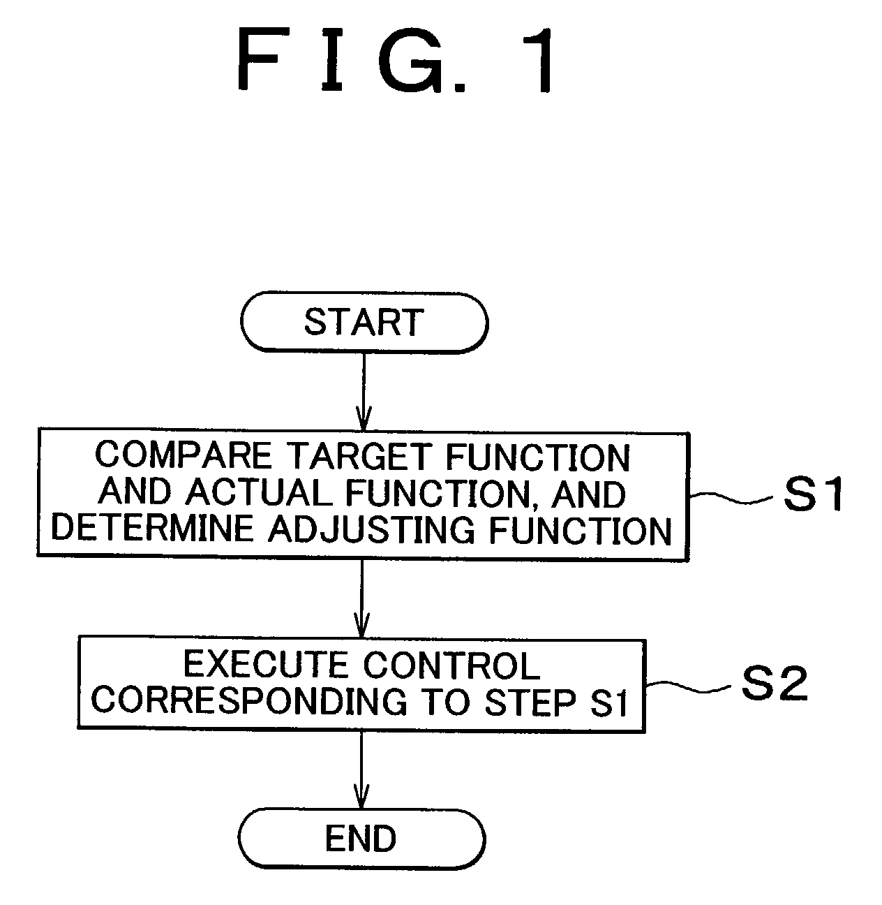
[0133]A third embodiment is concerned with an exemplary method of calculating a target regenerative braking force and a target torque of the motor-generator 11 that is performed in step S1 in FIG. 1. The third embodiment is applicable to, for example, the vehicle A1 shown in FIG. 4.
[0134]An overall construction of the control of the third embodiment will be described with reference to the flowchart shown in FIG. 10. First, in step S11, states of the vehicle A1 is determined. In step S11, (1) a torque generated by the engine 3, (2) a transfer coefficient of the clutch 7, and (3) a driving force of the vehicle A1 provided by the engine torque are calculated. The item (1) is calculated on the basis of the engine speed, and the amount of intake air. The item (2) is calculated on the basis of the torque transfer power (engagement pressure) of the clutch 7, the friction coefficients of friction members of the clutch 7, etc. The item (3) is calculated by multiplying...
PUM
 Abstract
Description
Claims
Application Information