
Passive deployment mechanism for space tethers

a technology of space tethers and passive deployment, which is applied in the direction of space vehicles, transportation and packaging, aircrafts, etc., can solve the problems of high deployment friction force, rather strong mechanical complications, and slow orbital change, and achieve the effect of low friction force and minimal complexity

Inactive Publication Date: 2007-02-20
SELENIA SPAZIO SPA
View PDF5 Cites 13 Cited by
  • Summary
  • Abstract
  • Description
  • Claims
  • Application Information

AI Technical Summary

Benefits of technology

Enables efficient, low-friction passive deployment of long tethers up to 20-30 kilometers with minimal complexity and mass, reducing the risk of failure and achieving high deployment rates of up to ten meters per second as gravity gradient tensions increase.

Problems solved by technology

Analyses show that the use of tethers for orbital adjustment is far more efficient in terms of spacecraft mass requirements than the use of chemical thrusters, though the orbital changes are also slow.
None of these tether mechanisms has the characteristics or advantages of the mechanism and deployment method disclosed here, which allow the deployment of a full passive space tether from an orbiting spacecraft carrier, starting from the early stage of deployment, when gravity gradient tensions are still very low.
Consequently, even with its minimum winding of tether spirals onto the “barber pole” during early tether deployment phases, some high residual tether deployment friction force is always present in this type of mechanism, making very difficult if not impossible an early stage passive space tether deployment performance, as that which can be obtained by the mechanism disclosed in the present application.
On the other hand, the ATEX mechanism indicated in Ref. 4. above, is not designed for cable tether but for tape tether, with tether reel and motor and hence very high deployment friction force and rather strong mechanical complications, not at all present in the mechanism described in the present application.
However, the experiment was a complete failure, with only 22 meters of the tether being successfully deployed before STEX determined an out-of-bounds condition with tether deployment.

Method used


Image

  • Passive deployment mechanism for space tethers
  • Passive deployment mechanism for space tethers
  • Passive deployment mechanism for space tethers

Examples


Embodiment Construction

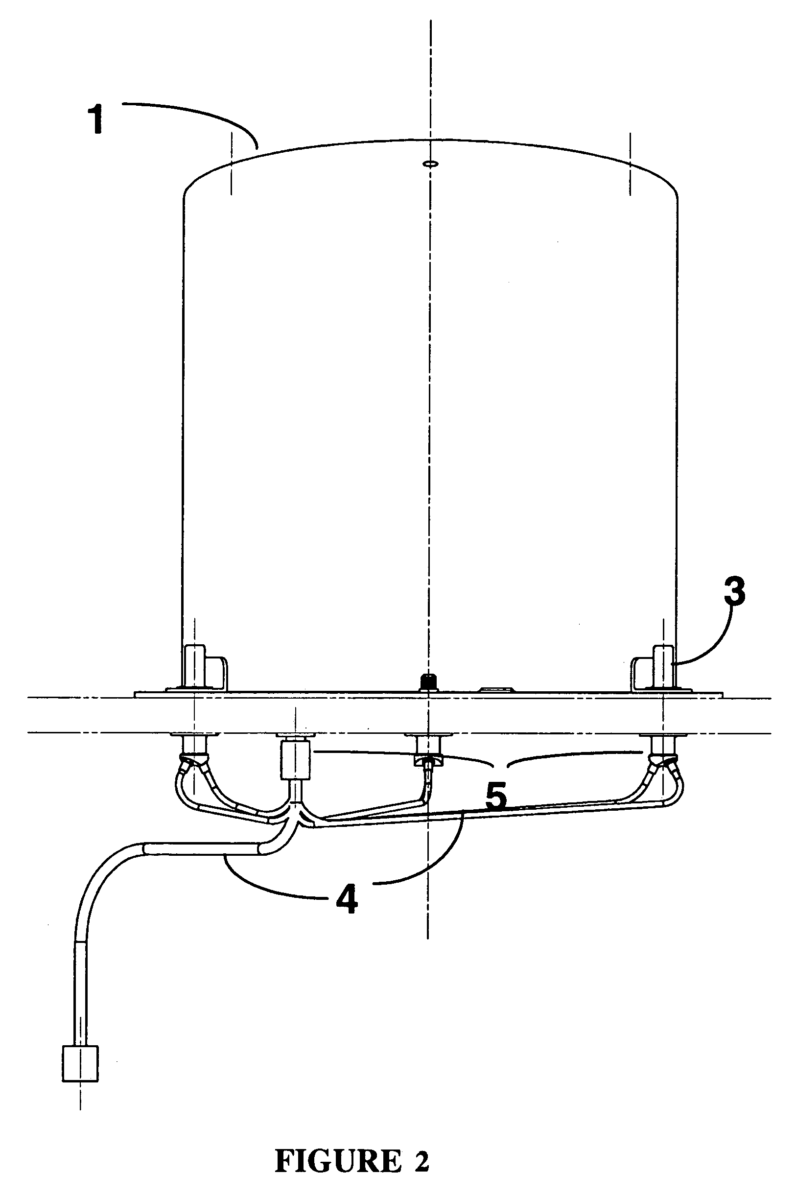
[0038]The mechanism described here may be fitted onto a satellite bus with minimum mass, complexity and cost, as it limits the number of tether deployment mechanism components to a minimum, while minimising the risk of failure. Minimum electrical and mechanical or structural interfaces are required, as also shown in FIGS. 2 and 4.

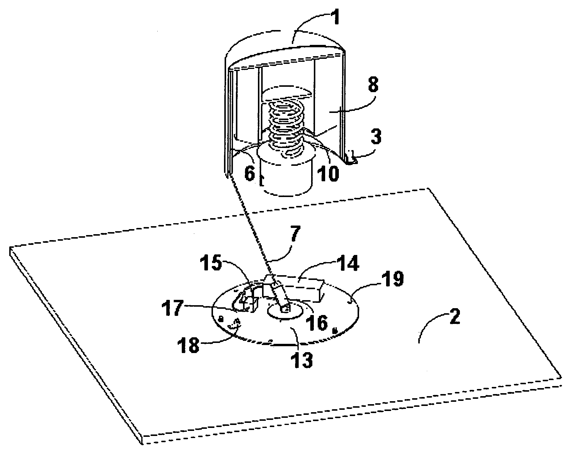
[0039]In the mechanism described here, the impulse for the separation and starting of the on-orbit tether deployment is provided by a simple system illustrated in FIG. 3, with a spring 10 accommodated at the centre of the fixed tether spool 8 and attached to it by a mechanical interface plane 11. When the deployer cover 1 is freed by the simultaneous actuation of the (three) pyro-bolts 3 through a suitable ground command, the central separation spring is freed at one end and hence imparts the planned impulse to the tethered deployer mass and transforms its stored energy in form of kinetic energy of the tethered masses.

[0040]As shown in FIG. 4, after the act...


PUM


Abstract

Mechanism for passively deploying expendable space tethers on orbit, by means of an initial separation impulse only, provided by a simple spring system that is part of the mechanism itself. The passive deployment of the space tether and a tethered end-mass is provided by the particular mechanism devised, having very low deployment friction and resistance. Tether deployment brake towards the final part of deployment is produced by a daisy-like brake, stored within the winding of the fixed tether spool so that it is automatically deployed (opened) and starts its deployment braking or resistance function from a planned point of the tether deployment in space.

Description

CROSS REFERENCE TO RELATED APPLICATIONS[0001]This application is the US national phase of PCT application PCT / IT2004 / 000638 filed 18 Nov. 2004 with a claim to the priority of Italian patent application RM2004A000153 itself filed 24 Mar. 2004.BACKGROUND OF THE INVENTION[0002]1. Field of the Invention[0003]The present invention relates to the field of the mechanisms for deployment of space tethers from earth orbiting spacecraft or satellite carriers and in particular to the class of expendable tether mechanisms for passive on orbit deployment of end-masses tethered by a long space tether and that do not require to be retrieved. Tethers many kilometres in length, to be stored by winding up onto the present mechanism, may be either conductive, usually made of copper or aluminium, or non-conductive, such as those made of Kevlar, Spectra, glass fibre, quartz fibre, etc. depending on the space tether application.[0004]One of the most important issues for an application requiring a tether m...

Claims


Application Information

Patent Timeline
Patent Type & Authority Patents(United States)
IPC IPC(8): B64G1/22B64G1/64
CPCB64G1/648B64G1/222B64G1/2228
Inventor LICATA, RENATO
Owner SELENIA SPAZIO SPA
Learn More