AI technical title is built by Patsnap AI team. It summarizes the technical point description of the patent document.
a coiled-sheet stent, strong technology, applied in the field of stent grafts, can solve the problems of uneven stent structure expansion and/or balloon rupture, less flexible graft prosthesis, and exposed damaged vessel walls, etc., to achieve sufficient resilience and flexible graft prosthesis, facilitate articulation
Inactive Publication Date: 2007-02-20
ENDOTEX INTERVENTIONAL SYST
View PDF85 Cites 98 Cited by
Summary
Abstract
Description
Claims
Application Information
AI Technical Summary
This helps you quickly interpret patents by identifying the three key elements:
Problems solved by technology
Method used
Benefits of technology
Benefits of technology
[0017]Thus, a stent-graft in accordance with the present invention may have a substantially flexible region that may conform substantially to the anatomy of a treatment site. Preferably, the flexible region is defined by an exo-skeleton attached to a tubular graft that includes one or more serpentine elements. The serpentine elements may facilitate articulation between adjacent serpentine elements, and / or may be sufficiently resilient and flexible to allow articulation, compression and / or expansion of the serpentine elements themselves.
Problems solved by technology
One problem often associated with such prostheses is effectively securing the tubular graft at the treatment site.
The released graft prosthesis may not sufficiently engage the vessel wall adjacent the treatment site, possibly resulting in the graft prosthesis moving after implantation, which may expose the damaged vessel wall.
Such expandable structures, however, may require the use of a balloon or other expandable member to expand the stent structure to the enlarged condition, which may introduce risks of uneven stent structure expansion and / or balloon rupture.
A coiled-sheet stent, however, may be substantially rigid transverse to its longitudinal axis, potentially resulting in a less flexible graft prosthesis, which may not be implanted effectively in tortuous anatomical conditions.
Method used
Image
Click on the blue label to locate the original text in one second.
Reading with bidirectional positioning of images and text.
Examples
Embodiment Construction
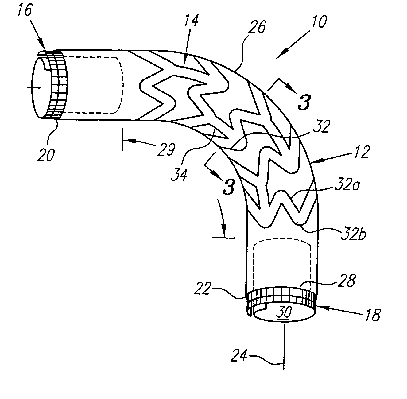
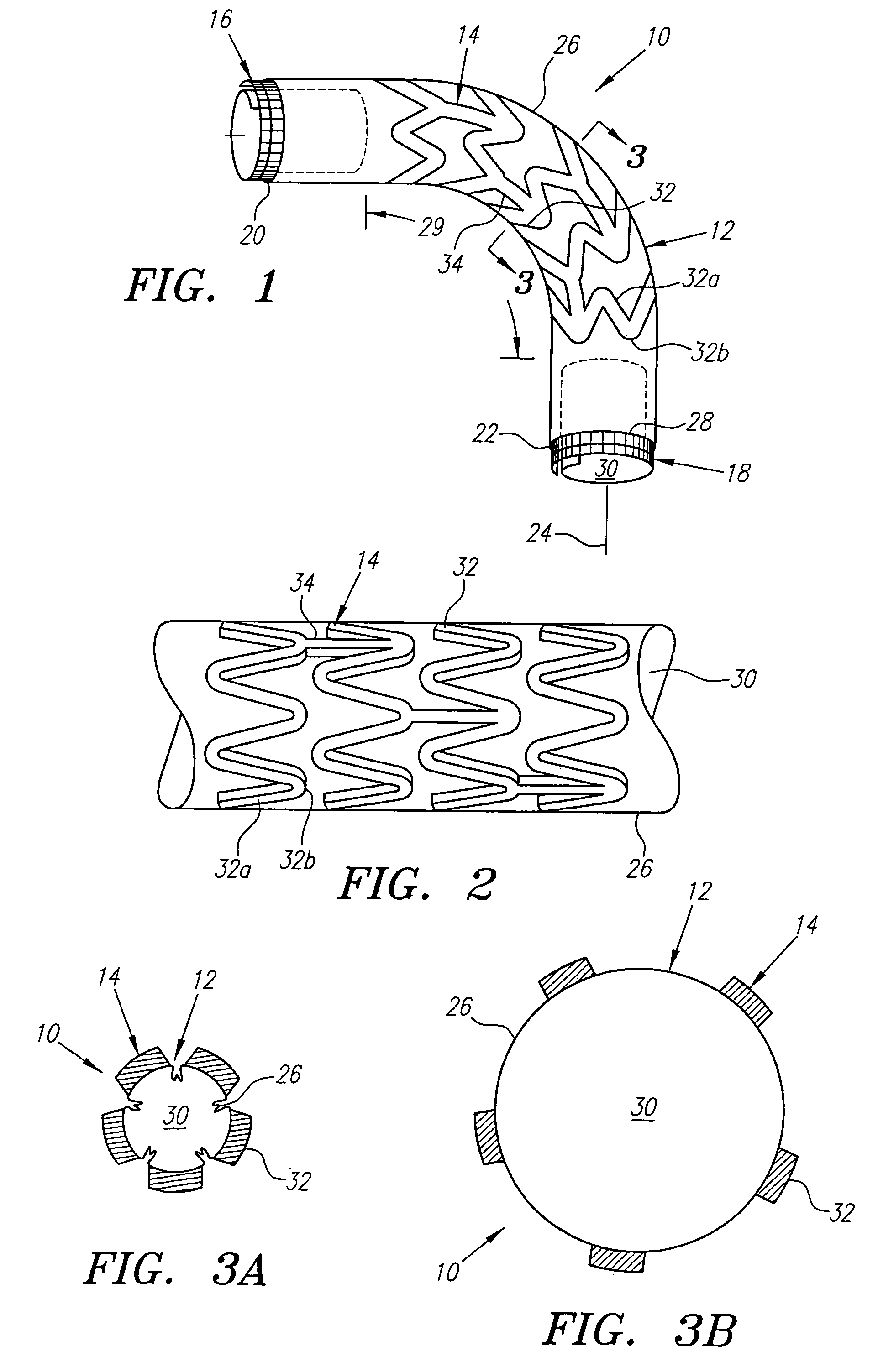
[0031]Turning now to the drawings, FIG. 1 shows a first preferred embodiment of a stent-graft 10 in accordance with the present invention that includes a tubular graft 12, an exo-skeleton 14, and first and second coiled-sheet stents 16, 18. The tubular graft 12 has first and second ends 20, 22 defining a longitudinal axis 24 therebetween and a peripheral wall 26 defining a periphery 28 and a lumen 30 therein. The tubular graft 12 may be formed from a variety of biocompatible materials, preferably a polymeric material, such as polyester, polytetrafluorethaline, dacron, teflon, and polyurethane.
[0032]The exo-skeleton 14 is attached to the peripheral wall 26 and includes a plurality of serpentine elements 32. The exo-skeleton 14 may be formed from a variety of semi-rigid materials, preferably a biocompatible metallic material, such as Nitinol or stainless steel. The material may be resiliently deformable, may exhibit shape memory properties and / or may be plastically deformable, as desc...
PUM
Abstract
A stent-graft having an exo-skeleton attached to a tubular graft, the tubular graft having a peripheral wall defining a lumen therein extending between first and second ends. The exo-skeleton may assume contracted and enlarged conditions, and includes one or more serpentine elements, each extending both peripherally and axially along at least a portion of the peripheral wall. Coiled-sheet stents are provided on the ends of the tubular graft for anchoring the ends within a body passage. Each serpentine element is a zigzag structure extending peripherally about the peripheral wall, with a plurality of serpentine elements distributed axially along the peripheral wall. The serpentine elements are individually attached to the peripheral wall and / or connector elements may extend between adjacent serpentine elements. Alternatively, each serpentine element may define a generally sinusoidal shape extending axially along the peripheral wall. The tubular graft may have a bifurcated end from which a tubular graft extension segment may extend and to which a docking limb may be attached. A plurality of serpentine elements may also be attached to the extension segment and the docking limb.
Description
[0001]This application is a continuation of application Ser. No. 09 / 932,079, Filed Aug. 17, 2001, now U.S. Pat. No. 6,632,240 which is a continuation of application Ser. No. 09 / 406,984, filed Sep. 28, 1999, now U.S. Pat. No. 6,290,720, which is a divisional of application Ser. No. 09 / 192,977, filed Nov. 16, 1998, now U.S. Pat. No. 6,325,820, the disclosure of which is expressly incorporated herein by reference.FIELD OF THE INVENTION[0002]The present invention relates generally to prostheses for implantation with body lumens, and more particularly to a stent-graft having a flexible exo-skeleton attached to a tubular graft.BACKGROUND[0003]Graft prostheses are often implanted within blood vessels, particularly the aorta or other arteries, which may be subject to aneurysm formation and / or severe atherosclerotic disease which may involve multiple stenoses. For example, an aortic aneurysm may develop in a patient, for example, within the abdominal aorta at the aorto-iliac bifurcation, req...
Claims
Application Information
Patent Timeline
Application Date:The date an application was filed.
Publication Date:The date a patent or application was officially published.
First Publication Date:The earliest publication date of a patent with the same application number.
Issue Date:Publication date of the patent grant document.
PCT Entry Date:The Entry date of PCT National Phase.
Estimated Expiry Date:The statutory expiry date of a patent right according to the Patent Law, and it is the longest term of protection that the patent right can achieve without the termination of the patent right due to other reasons(Term extension factor has been taken into account ).
Invalid Date:Actual expiry date is based on effective date or publication date of legal transaction data of invalid patent.

