Enhanced antenna stowage and deployment system

a deployment system and antenna technology, applied in the direction of collapsible antenna means, antenna details, antennas, etc., can solve the problems of reducing the number and types of missions which can be performed by satellites, reducing the flexibility and configuration of appendages, and increasing spacecraft volume and mass. , to achieve the effect of enhancing the antenna stowage and deployment system

Active Publication Date: 2007-02-20
LOCKHEED MARTIN CORP
View PDF5 Cites 40 Cited by
  • Summary
  • Abstract
  • Description
  • Claims
  • Application Information

AI Technical Summary

Benefits of technology

[0002]The present invention generally relates to an enhanced antenna stowage and deployment system and, more particular...

Problems solved by technology

Due to design limitations, antennas are conventionally stowed and deployed at different locations on a spacecraft when there are more than two antennas.
To its disadvantage, however, the conventional antenna stowage and deployment system utilizes nesting antennas 102 to 105 which are positioned on obverse sides of spacecraf...

Method used


Image

  • Enhanced antenna stowage and deployment system
  • Enhanced antenna stowage and deployment system
  • Enhanced antenna stowage and deployment system

Examples


Embodiment Construction

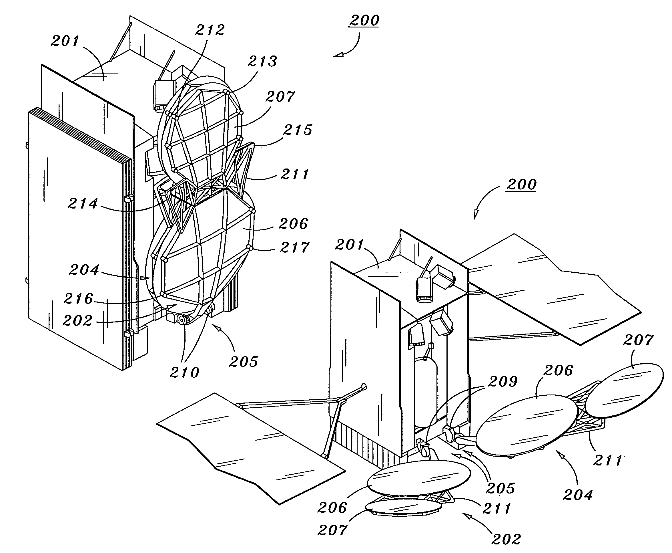
[0021]The present invention relates to an improved antenna stowage and deployment system for a spacecraft with more than two antennas, which allows for a plurality of antennas to be placed in the same location on a spacecraft, minimizing the volume of the system and reducing the number of necessary launch restraints.

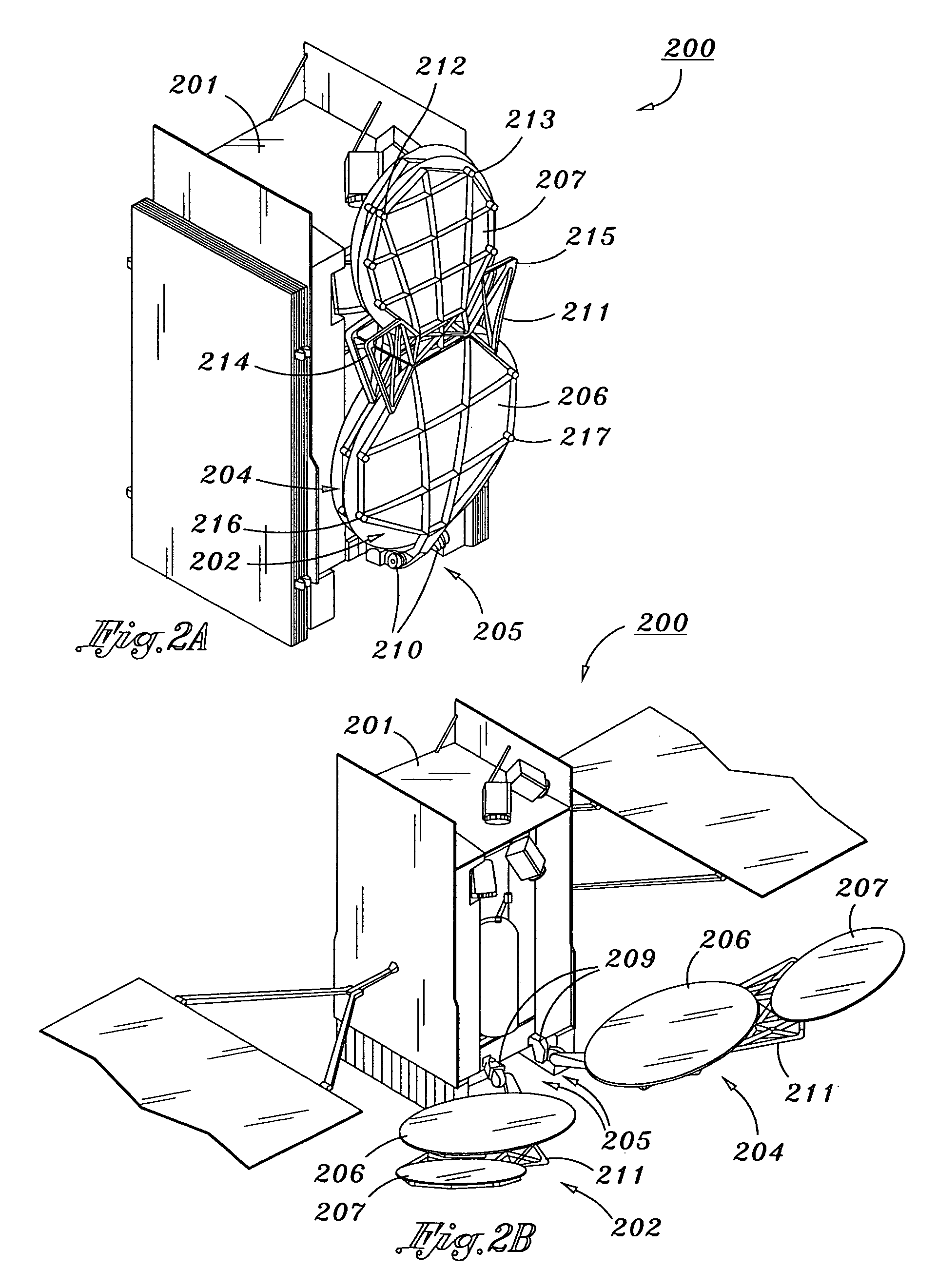
[0022]FIGS. 2A and 2B illustrate the enhanced antenna stowage and deployment system according to one embodiment of the present invention, in a state where the antenna assemblies are stowed and deployed, respectively. Briefly, the antenna stowage and deployment system according to this first example embodiment of present invention includes a spacecraft and at least one pair of adjacent nesting antenna assemblies. Each of the antenna assemblies further includes an articulating deployment couple affixed to the spacecraft for deploying the antenna assembly, a first antenna affixed to the deployment couple, and a second antenna affixed to the first antenna. At least one of th...


PUM


Abstract

An antenna stowage and deployment system, including a spacecraft and at least one pair of adjacent nesting antenna assemblies. Each of the antenna assemblies further includes an articulating deployment couple affixed to the spacecraft for deploying the antenna assembly, a first antenna affixed to the deployment couple, and a second antenna affixed to the first antenna. The enhanced antenna stowage and deployment system according to the present invention permits the separation and orientation of more than two adjacent antennas which require an extremely precise deployed position relative to a main spacecraft body. As such, the deployment couple further includes a 1-axis separating hinge and/or a 2-axis primary deployment gimbal. At least one of the antenna assemblies further includes a 2-axis secondary deployment gimbal or a rigid connecting structure for affixing the second antenna to the first antenna.

Description

STATEMENT AS TO RIGHTS TO INVENTIONS MADE UNDER FEDERALLY SPONSORED RESEARCH OR DEVELOPMENT[0001]Not ApplicableFIELD OF THE INVENTION[0002]The present invention generally relates to an enhanced antenna stowage and deployment system and, more particularly, relates to the deployment of a pair of adjacent, gimbaled and nested antenna assemblies each comprising multiple antennas.BACKGROUND OF THE INVENTION[0003]In the development of satellite technologies, antenna flexibility, configurability, and aperture size affect the types of missions which can be performed by the satellite and define the variety of environments in which the satellite can operate. As more exotic mission applications are developed, antennas and antenna deployment subsystems need to be optimized to specifically tailor satellites to particular missions.[0004]As spacecraft capabilities and mission applications require increased information transmission capabilities, multiple large-aperture deployable antennas have been...

Claims


Application Information

Patent Timeline
IPC IPC(8): H01Q3/02
CPCH01Q1/08H01Q1/288Y10S343/02
Inventor HENTOSH, DAVID J.
Owner LOCKHEED MARTIN CORP
Why Eureka
Try Eureka