Holder/optical-element assembly

a technology of optical elements and assemblies, applied in glass making apparatuses, instruments, manufacturing tools, etc., can solve problems such as potential problems in optical performance and positioning, deterioration of optical quality of optical elements, etc., and achieve the effect of precise optical elements and substantial precision

Active Publication Date: 2007-02-20
ALPS ALPINE CO LTD
View PDF15 Cites 10 Cited by
  • Summary
  • Abstract
  • Description
  • Claims
  • Application Information

AI Technical Summary

Benefits of technology

[0014]Accordingly, the plurality of openings may support the volume error of the optical-element material during the press-molding of the optical element to achieve a substantial precision in the formation of the optical-element, thereby providing a holder / optical element assembly having a substantially precise optical element without requiring further improvement to the precision of the holder.

Problems solved by technology

This may not only deteriorate an optical quality of the optical element, but also may require adjustment and fixing to an appropriate optical position, thus causing potential problems in terms of optical performance and positioning.

Method used


Image

  • Holder/optical-element assembly
  • Holder/optical-element assembly
  • Holder/optical-element assembly

Examples


Embodiment Construction

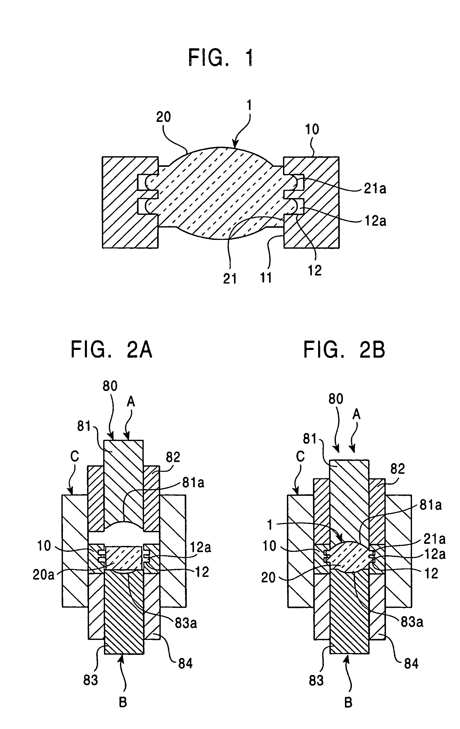
[0022]Embodiments of the present invention will be described below with reference to the drawings. A first embodiment will now be described. FIG. 1 is a cross-sectional view of a holder / optical-element assembly 1 according to the first embodiment of the present invention. FIGS. 2A and 2B are cross-sectional views illustrating two manufacturing steps during an assembly of the first embodiment of FIG. 1.

[0023]The assembly 1 may be used in, for example, a digital camera or a pickup head of a CD player. Referring to FIG. 1, the assembly 1 includes a cylindrical lens holder 10 and a spherical lens 20 that is disposed within the lens holder 10.

[0024]The lens holder 10 holds the lens 20 and provides the positioning of the lens 20 in an optical apparatus. The lens holder 10 is formed by, for example, cutting or casting a material such as aluminum and stainless steel. The lens holder 10 is provided with openings 12, namely engagement grooves 12a, along the inner periphery surface 11 of the l...


PUM

PropertyMeasurementUnit
sizeaaaaaaaaaa
porosityaaaaaaaaaa
porosityaaaaaaaaaa

Abstract

A holder/optical-element assembly includes a holder and an optical element disposed within the holder. The holder has an inner periphery surface in which at least one opening is provided, and the optical element is formed with at least one protrusion extending outward from an outer periphery of the optical element. The protrusion of the optical element is engaged with the opening of the holder.

Description

[0001]This application claims the benefit of priority under 35 U.S.C. 119 (a)–(d) to Japanese Patent Application 2003-060947, which was filed on Mar. 7, 2003.BACKGROUND OF THE INVENTION[0002]1. Field of the Invention[0003]The present invention relates to holder / optical-element assemblies in which an optical element is integrated with a holder, and particularly, to a holder / optical-element assembly formed by press-molding an optical-element material.[0004]2. Description of the Related Art[0005]Optical elements, such as lenses used in digital cameras and in pickup heads of CD players, require high precision when installed. As disclosed in, for example, Japanese Patent No. 2729702, a substantially—precise installation is generally achieved by forming a holder / optical-element assembly, in which the optical element is held by the holder, and then adjusting a position of the holder during the installation. In this holder / optical-element assembly, the optical element is formed by setting a...

Claims


Application Information

Patent Timeline
Patent Type & Authority Patents(United States)
IPC IPC(8): G02B7/02C03B11/08
CPCC03B11/08G02B7/022C03B2215/46C03B2215/79C03B2215/73
Inventor KIKUCHI, KIMIHIRO
Owner ALPS ALPINE CO LTD
Why Eureka
Try Eureka