Directly detection device of trajectories of drops issuing from liquid jet, associated electrostatic sensor, print head and continuous ink jet printer

a technology of direct detection and drop issuing from liquid jet, which is applied in the direction of printing, electrostatic field measurement, instruments, etc., to achieve the effect of easy perturbation

Active Publication Date: 2013-08-20
MARKEM IMAJE HLDG
View PDF26 Cites 6 Cited by
  • Summary
  • Abstract
  • Description
  • Claims
  • Application Information

AI Technical Summary

Benefits of technology

[0056]on the other hand, the drops must pass as closely as possible to the flat surface of the sensor to produce good signal / noise ratio and therefore precise measurements.
[0064]With respect to manufacturing an electrostatic sensor according to the invention, a conductive pass through is preferably made in a small insulating plate in a zone intended to be the sensitive surface. The assembly is preferably metallised on the two faces and at least on one edge of the plate, then etched locally to remove the metallisation on the patterns representing the insulating zones of the flat functional surface and to insulate the area where the conductive pass through terminates on the rear face. The shielding of the flat functional surface extends therefore over the majority of the rear face, ensuring optimal electric protection of the sensitive zone. The conductive pass through transfers the electric continuity of the sensitive zone to the rear of the plate where it is taken up by an adapted terminal. The plate is then preferably fixed tightly and in reference on a casing. When the electrostatic sensor according to the invention is implanted in a continuous jet print head, this casing will itself be mounted in reference on the one hand relative to the gutter and on the other hand relative to the nominal trajectory of non-deflected jet (in fact, the mechanical reference structure of the head).
[0075]The electrostatic sensor is arranged preferably close to and upstream of the recovery gutter of non-deflected drops. Thus, the downstream edge of the sensitive zone is preferably distant from the inlet plane of the gutter by a minimum distance between 0.5 mm and 5 mm, for a drop diameter of between 70 μm and 250 μm. In fact, the downstream edge of the sensor must be as close as possible to the opening of the gutter to have maximum precision in the evaluation of the detection surface. This also helps enlarge the sensitive zone to the maximum with gains on several parameters, such as the Signal / Noise ratio, the jet / sensor distance, . . . . On the contrary, there is a risk of fouling when the drops arrive at high speed on contact inside the gutter: droplets can splash out of the gutter and foul the sensor. The sensor must therefore be sufficiently far from the gutter to be out of reach of these splashing droplets. In practice, the compromise of distance defined hereinabove has proven optimal for a drop diameter of between 70 μm and 250 μm, effectively corresponding to the types of drops issuing from a continuous ink jet of a printer. A first arrangement of the sensor made in the print head is such that its flat surface is substantially perpendicular to the deflection plane of the drops and opposite the directions of deflection defined as being the directions between zero deflection trajectory and the plurality of deflection trajectories caused by the deflection electrodes during printing.
[0076]Another arrangement made of the sensor is such that its flat surface is substantially parallel to the deflection plane of the drops and to the rear of the ink jet, the front of the ink jet being defined in reference to the front face of the head. With these two arrangements, accessibility for maintenance of the print head is optimal.
[0085]On the other hand, without increasing the complexity of a print head such as described earlier, that is, by using a single electrostatic sensor, the processing of signals from the sensor likewise searches for the best phase of charge synchronisation and measures the speed of drops in the jet.

Problems solved by technology

These changes can be caused in particular by modification of the surface conditions in and around the nozzle caused by accumulation of ink fouling.
This problem becomes particularly sensitive after long periods of operation of the printer.
Some phases produce mediocre or even very poor charge synchronisation, but in general, a certain number of phases permits maximum charge.
On the contrary, the disadvantage here is to expose the sensor to significant electrostatic perturbations, especially generated by the noise produced by the circulation of charged drops in the internal environment of the print head and by the noise emitted by the different internal components of the head, which are subjected to variable or noisy electric voltages.
These conditions do not allow very precise measurements due to the very noisy signal of the sensor.
If this ink escapes the gutter, the jet must be stopped to avoid fouling of the print head and its environment, fouling being generally unacceptable to the user of the printer.
These problems can be created by deficiency of the recovery device which is incapable of evacuating the ink of the non-printed drops or by abnormal behaviour of the jet.
On the contrary, dysfunctioning appears when the trajectory of the jet exits from the gutter or when drops strike its edge.
Unfortunately, the system can be faulty since it cannot generally make the difference between the case of correct functioning and that where the jet, when improperly oriented, strikes the edge of the gutter.
So, in a situation where the jet is improperly oriented all or part of the ink of the jet contaminates the immediate environment of the edge of the gutter, or flows inside the gutter, which generally results in major dysfunction after it accumulates.
The detection of correct recovery of the ink inside the gutter is therefore not reliable with solutions of the prior art.
The localisation of ink drops by physical contact on a pressure sensor or by means of optical barriers is not reliable under industrial conditions of use of ink jet printers, due in particular to the sensitivity of such solutions to fouling by ink.
Using this principle on a continuous ink jet print head leads to complex, bulky and costly implementation.
This realisation causes other disadvantages:on the one hand, the use of four sensors placed around the jet cannot be done without partially masking visibility the jet which is confined at the level of the sensors in a narrow space, difficult to access for maintenance of the print head, especially for cleaning the charge or deflection elements;on the other hand, the means which are dedicated to measuring the orientation drift of the jet must be inserted along the trajectory of the jet between the nozzle and the recovery gutter.
The intrinsic bulkiness of the sensors generates problems of physical integration and tends to increase the distance of flight of the drops between their charge and their impact locations on the medium to be printed.
The drawback is that a long distance of flight of drops impairs position precision of impacts and therefore the printing quality.
In summary, the major disadvantages of recovery detection solutions of drop coming from liquid jet according to the prior art are the following:detection of the passage of the ink in the gutter by means of a sensor analysing the ink flow in the fluid vein in the gutter is not enough to prevent pollution risks because when the jet strikes the edge of the gutter it is not detected as a defect situation,evaluation of the real position of the drops, at the level of a plane perpendicular to the nominal trajectory of the jet and in the vicinity of the inlet of the gutter, is possible with solutions of the art using several pairs of electrostatic sensors but at the price of significant bulkiness and at prohibitive cost;arrangement of two pairs of electrostatic sensors around the jet makes it very difficult to access the different functional means of the head for maintenance, especially for cleaning;using sensors dedicated to measuring orientation shifts of the jet on the trajectory of the jet makes the drop flight paths longer in the print head to the detriment of the print quality;using electrostatic sensors easily perturbated by noise coming from different electric signals of the print head and from electric charges in movement in the print head affects measurement precision.
It is frequently necessary to either create effective shielding, often in a bulky manner, of the sensitive parts of the sensor, or to perform additional processing of the signal produced, which proves costly.

Method used


Image

  • Directly detection device of trajectories of drops issuing from liquid jet, associated electrostatic sensor, print head and continuous ink jet printer
  • Directly detection device of trajectories of drops issuing from liquid jet, associated electrostatic sensor, print head and continuous ink jet printer
  • Directly detection device of trajectories of drops issuing from liquid jet, associated electrostatic sensor, print head and continuous ink jet printer

Examples


Embodiment Construction

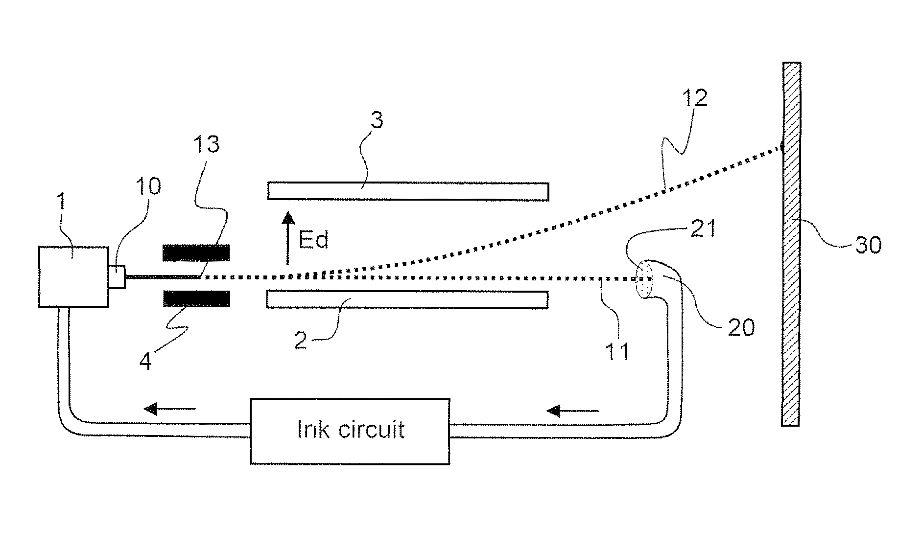
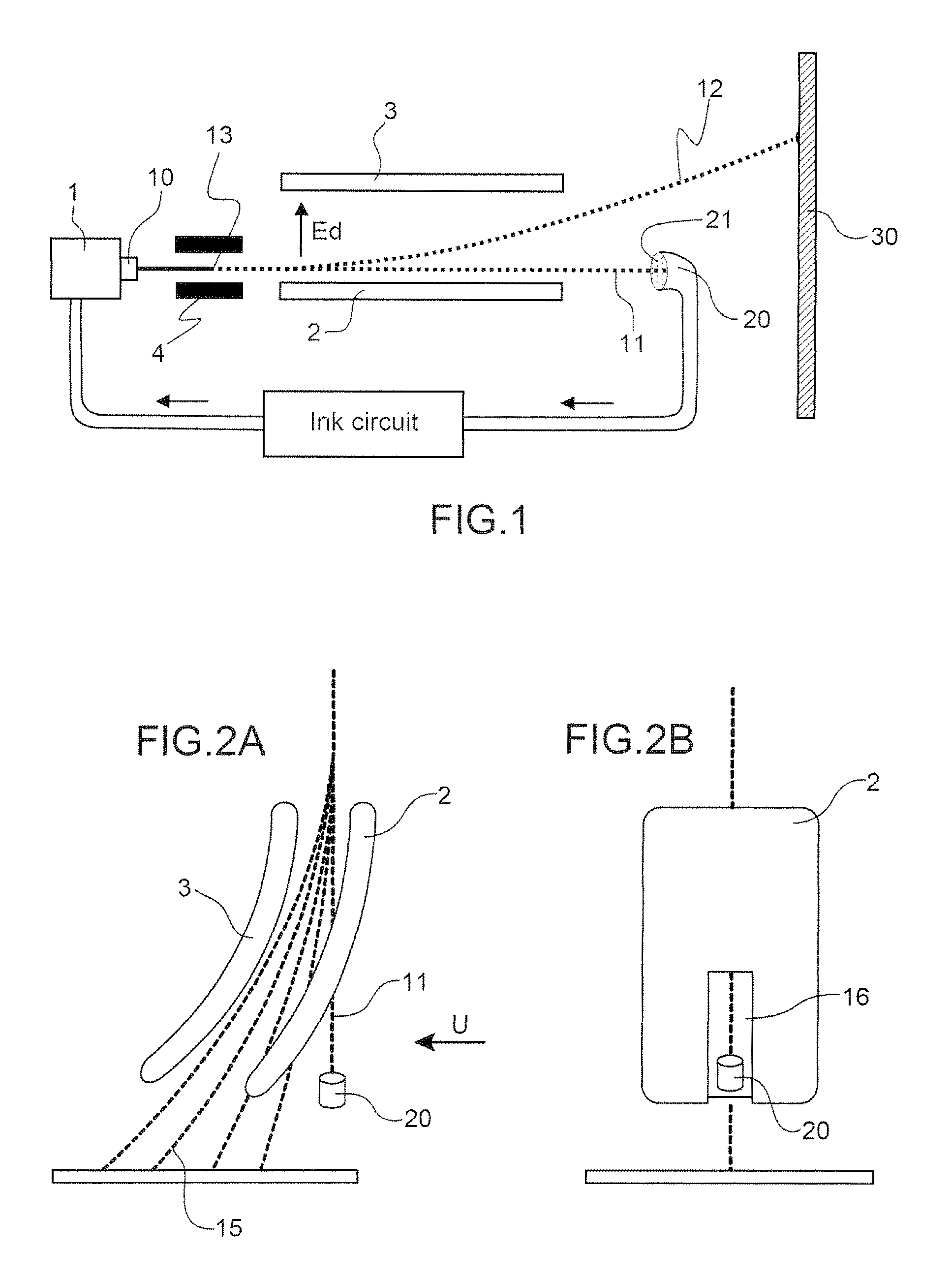
[0102]FIGS. 1 to 2B relative to a print head using deflected continuous ink jet technology according to the state of the art have already been commented on in the preamble, and are not explained here further in terms of the functions of the different means.

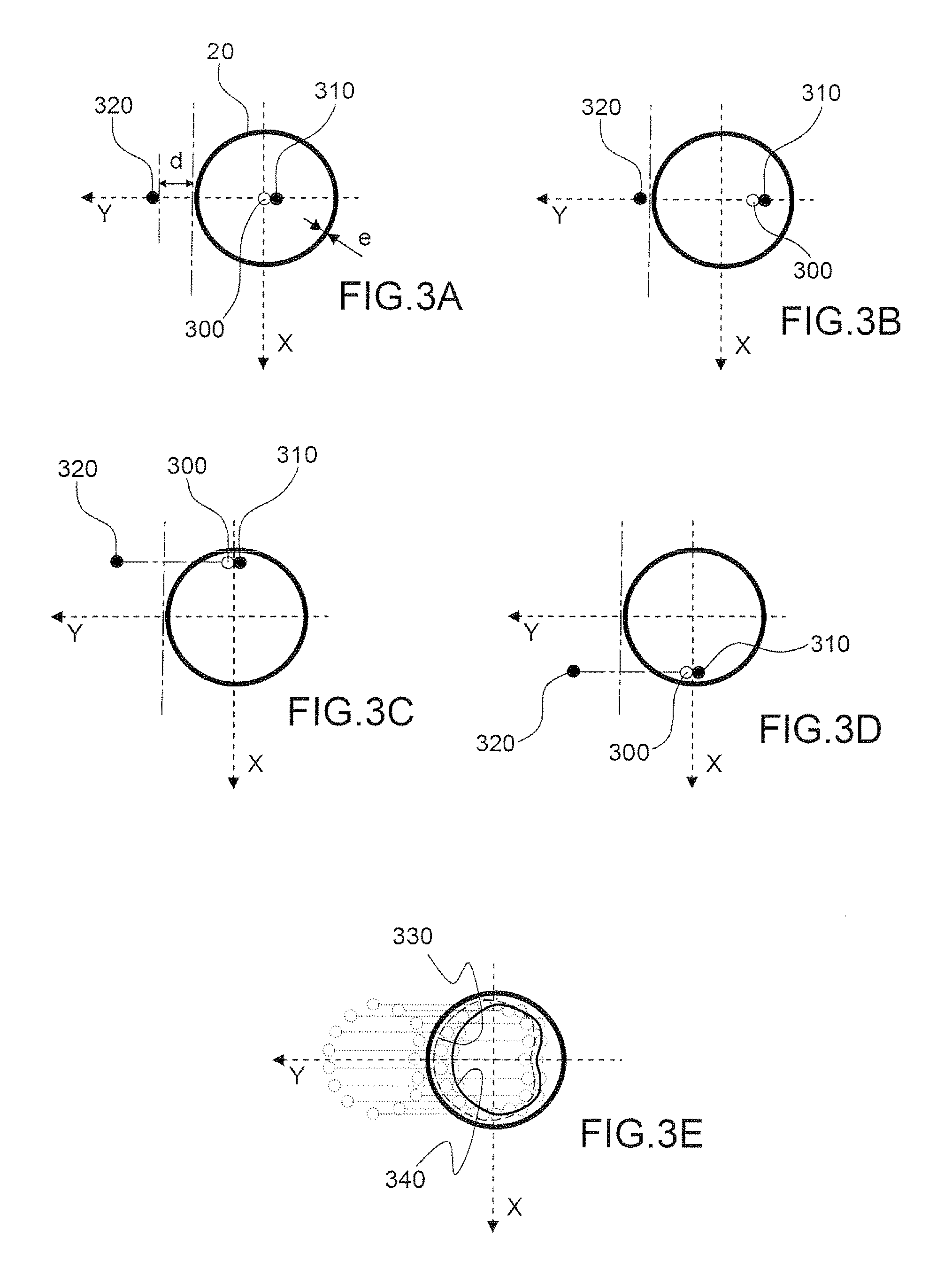
[0103]The problem with which the inventors have been confronted is the following: theoretically, the trajectory of non-deflected drops referenced by 11 in these FIGS. 1 to 2B is unique and passes through the centre of the inlet 21 of the recovery gutter 20. In fact, as indicated in the preamble of the application, it can eventuate at any instant during printing that the non-deflected drops take different trajectories around this nominal trajectory. This may be due to manufacturing and assembly tolerances of the different functional means of the head, or to the random conditions for setting up the jet at start-up of printing or likewise to progressive fouling, for example of the ejection nozzle, which results in slow change of the ...


PUM


Abstract

Systems and methods for detection of the directivity of trajectories of charged drops issuing from a jet are disclosed. According to one aspect, an electrostatic sensor is disclosed which includes a flat functional surface. The electrostatic sensor is configured to function in a non-differential manner and has a geometric shape and arrangement that are substantially aligned relative to a nominal trajectory of drops. A trajectory of drops can be followed at the same time in a plane parallel to the flat surface of the sensor and in a plane perpendicular to the flat surface of the sensor. As a result, it can be verified whether a drop is present or remains in a predefined monitoring zone. According to another aspect, a method of controlling trajectories of drops in a print head having a continuous deflected jet, and a method of monitoring the effective recovery by the gutter of drops not intended for printing are disclosed.

Description

RELATED APPLICATIONS[0001]This application is a U.S. National Phase of International Application No.: PCT / EP2010 / 060942, filed Jul. 28, 2010, which claims the benefit of U.S. Patent Application No. 61 / 243,513 filed Sep. 17, 2009 and French Patent Application No. 09 55362 filed Jul. 30, 2009, each of which is incorporated by reference in their entirety.FIELD OF THE INVENTION[0002]The invention relates to a directivity detection device of trajectories of drops issuing from a liquid jet.[0003]More particularly, it deals with control of the functioning of a continuous ink jet print head.[0004]The invention detects whether the drops not printed and issuing from a continuous ink jet are effectively or not directed to the recovery gutter of these drops. It likewise determines the charge synchronisation of drops and allows to know the speed of drops issuing from the continuous jet.[0005]The invention likewise relates to an associated electrostatic sensor, print head and printer with continu...

Claims


Application Information

Patent Timeline
Patent Type & Authority Patents(United States)
IPC IPC(8): B41J2/125
CPCB41J2/09B41J2/12B41J2/085B41J2/125
Inventor ODIN, FLORENCE
Owner MARKEM IMAJE HLDG
Why Eureka
Try Eureka